CMF Low-Profile Cable Mount for Flat-Panels up to 55” INSTALLATION INSTRUCTIONS CREATING POSITIVE CUSTOMER EXPERIENCES 9531-058-001-00
CMF Contents Weight Limit............................................................................................................................................................... 2 Warning Statements.................................................................................................................................................. 2 Installation Tools...........................................................................................................................................
CMF Installation Tools The following tools may be required depending on your installation. Level Electronic Stud Finder ⅛” Drill Bit Hand Held Drill 2 1 Phillips Tip Screwdriver Pencil Tape Measure Hammer Parts List Make sure none of the Premier Mounts parts are missing and/or damaged before beginning installation. If there are, stop the installation and call Premier Mounts at (800) 368-9700.
CMF Features Premier Mounts’ Low-Profile Cable Mount for Flat-Panels up to 55" (CMF) makes installing a flat-panel as simple as hanging a picture frame. The CMF’s slim design and patent-pending magnetically assisted installation feature, MagnaGuide®, makes it the ideal flat-panel accessory for fast and simple installations. This cable mount easily installs on a single stud and to hold flat-panel displays up to 55”, or up to 65 lbs with a 200 × 200mm to 600 × 400mm VESA mounting pattern.
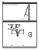
CMF Installing the Mount Sliding Plate to a Wood Stud ➊➊ Remove the mount sliding plate from the cable ➋➋ ➌➌ mounting plate (Figure 1). Use a stud finder and pencil to mark the center of a wall stud. Place the mount sliding plate on wall and align its screw holes with the center mark. Cable Mounting Plate The visual centering diamond on the mount sliding plate will help you determine where the center of the flat-panel will be on the wall (Figure 1).
CMF Attaching the Bolt Spindles to the Flat-Panel ➊➊ Refer to the flat-panel installation instructions to determine the type of screws you will use in the mounting installation. M4, M5, M6 and M8 screws are supplied with the CMF. Pan Combo Screw ➋➋ Insert the appropriate screw and spacer into each bolt spindle (Figure 1). Bolt Spindle Spacer If the flat-panel has a rear protrusion greater than the depth of the bolt spindles, attach one (1) spindle extension to each of the bolt spindles (Figure 2).
CMF Attaching the Bolt Spindles to the Flat-Panel (cont’d) ➊➊ Attach one (1) black vinyl cap to each of the bolt spindles (Figure 1). ➋➋ Pull on the crimp at the end of the cables to tighten the tension on the bolt spindle cabling (Figure 2). ➌➌ Wrap the excess cabling around the teeth on the cabling mounting plate, then tuck the crimp inside (Figure 3). Black Vinyl Cap Continue to the “Attaching the Flat Panel to the Wall” section below.
CMF Using the Kickstand Use the kickstand on the lower bolt spindle to prop up the flat-panel for easy power and cable management. Wall 90˚ 90˚ Kick Stand Side view of flat-panel and bolt spindles Technical Specifications All measurements are in inches [millimeters]. 1.28 32.43 .78 19.69 3.52 89.39 .57 14.58 SET AT 24" 3.52 89.39 6.09 154.80 Page 8 Visit the Premier Mounts website at http://www.premiermounts.
CMF Warranty PREMIER MOUNTS LIMITED LIFETIME WARRANTY What and Who is Covered by this Limited Warranty and for How Long Premier Mounts warrants this product to be free from defects in material and workmanship for the lifetime of the original owner of this product. The limited warranty is valid only for the original purchaser of the product. What Premier Mounts Will Do At the sole option of Premier Mounts, Premier Mounts will repair or replace any product or product part that is defective.