
Specifications


CMF
Page 6 Visit the Premier Mounts website at http://www.premiermounts.com Installation Instructions
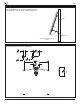
Attaching the Bolt Spindles to the Flat-Panel
Figure 2
Figure 3
Figure 5
➊
Refer to the at-panel installation instructions to
determine the type of screws you will use in the
mounting installation.
M4, M5, M6 and M8 screws are supplied with the
CMF.
➋
Insert the appropriate screw and spacer into each bolt
spindle (Figure 1).
If the at-panel has a rear protrusion greater than
the depth of the bolt spindles, attach one (1) spindle
extension to each of the bolt spindles (Figure 2).
The spindle extensions add ½" in depth.
➌
Attach the two (2) bolt spindles that are attached to
the cable mounting plate to the top two (2) mounting
locations on the back of the at-panel (Figure 3).
You may need to loosen the cabling by
simultaneously pushing down the lever on the back
of the cable mounting plate and pulling the bolt
spindle cabling (Figure 4).
➍
Attach the two (2) loose bolt spindles to the bottom two
(2) mounting locations on the back of the at-panel
(Figure 5).
Continue on page 7.
Figure 1
Bolt Spindle
Spacer
Pan Combo Screw
Bolt Spindle
Spindle Extension
X
X
X
X
Figure 4
Lever
Back view of cable mounting
plate