FPS-300 Installation Guide Installationsanleitung, Guía de Instalacíon, Guida de Installazione, Guide d’Installation, Installatie gids Warranty, Garantie, Garantía, Garanzia, Garantie, Waarborg: http://www.mounts.com/warranty www.mounts.com | North America 800.368.9700 | International +1-714-632-7100 1321 S. State College Blvd., Fullerton, CA 92831 USA 9535-000-011-0X Rev.
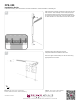
Included components x8 x6 M8 x 16mm M5 x 10mm x8 1/4” x4 x18 M3 x 8mm x20 x20 M4 x 5mm x2 #8 x 1-1/4” x5 x8 1/4” x 3” x1 #10 Required for installation 7/16” Note: If you are using the optional concealed left or right side power and signal box sections, install only one side of the upper track guide along with the power signal box cover that is opposite of where the power and signal is coming from.
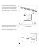
FPS-300 Installation Guide Installationsanleitung, Guía de Instalacíon, Guida de Installazione, Guide d’Installation, Installatie gids Take one 48 in. upper channel section (A) and place it horizontally on the wall and level at the desired height, in line with both the predetermined stud locations and with anchoring position in the far right or left slot. Mark through the upper channel mounting holes directly on the wall.
Once the mounting pilot holes have been drilled, take the first 48 in. (1219mm) section of mounting channel and secure it level on the wall with the mounting hardware provided. Once the first upper channel is secure, follow the same procedure for the second 48 in. (1219mm) upper channel. Do not overtighten the screws. 4 A: Make sure the two upper channel sections are locked together inside the locking tabs provided at the channel ends. Do NOT tap on the small protruding tabs.
FPS-300 Installation Guide Installationsanleitung, Guía de Instalacíon, Guida de Installazione, Guide d’Installation, Installatie gids 6 With both upper and lower channels level and secure to the wall, the main slider assembly can be raised (two people recommended) with the upper rollers properly seated into the upper channel receiver slots. Once fully seated, the lower rollers should be on center with the lower roller channel. 7 Install the power signal boxes to each end.
Using the spirit level supplied, adjust the stand off of the lower roller wheels to provide a level vertical for the slider frame on the wall. Loosen the locking screw at the bottom of the roller using a Phillips head screwdriver. Install the dome plug and tighten the bottom lock screw once the slider is level. 8 Use UL or VDE listed flexible electrical cord appropriate for this installation. (Contact your local electrician for more information).
FPS-300 Installation Guide Installationsanleitung, Guía de Instalacíon, Guida de Installazione, Guide d’Installation, Installatie gids 10 Remove the top cover on the slider assembly and set aside for later re-install. 11 Lay the plastic track glide unit with power and signal cable installed within track section fully inside the upper channel receiver section.
Secure both ends of the cable track system to the upper channel structure with the track brackets and hardware supplied as shown in the visual diagram. Secure the power strip to the frame using two (2) M3x8mm screws and two (2) M3 kep nuts. 12 x2 M5 x 10mm Double check all power and signal cables are properly secured to the system channels as to not cause any pinching of the cables during any movement of the slider system.
FPS-300 Installation Guide Installationsanleitung, Guía de Instalacíon, Guida de Installazione, Guide d’Installation, Installatie gids 13B Use additional tie wraps as needed for proper wire and cable routing. 14 Re-install the upper channel and end covers securely at this time. x2 M5 x 10mm Warranty: http://www.mounts.com/warranty Garantie, Garantía, Garanzia, Garantie, Waarborg Updates: The most up-to-date installation guides can be found at mounts.com 9535-000-011-0X Rev.2 www.mounts.
Install the power signal box covers and channel covers.
FPS-300 Installation Guide Installationsanleitung, Guía de Instalacíon, Guida de Installazione, Guide d’Installation, Installatie gids Refer to the “Universal Low Profile Flat Mount for 50″ to 80″ Flat Panels” for instruction on installing the display. 16 x8 M8 x 16mm x8 1/4” Warranty: http://www.mounts.com/warranty Garantie, Garantía, Garanzia, Garantie, Waarborg Updates: The most up-to-date installation guides can be found at mounts.com 9531-060-001-00 Rev.2 www.mounts.com | North America 800.
FPS-300 Installation Guide Installationsanleitung, Guía de Instalacíon, Guida de Installazione, Guide d’Installation, Installatie gids PREMIER MOUNTS LIMITED LIFETIME WARRANTY What and Who is Covered by this Limited Lifetime Warranty Premier Mounts warrants all mounting products to be free from defects in material and workmanship for the lifetime of the original installation of the product.