INSTALLATION INSTRUCTIONS GB-AVSTOR4 12” x 24” Ceiling Equipment Storage GearBox™ NORTH AMERICA 3130 East Miraloma Avenue Anaheim, CA 92806 USA USA and Canada Phone: 800.368.9700 Fax: 800.832.4888 Other Locations Phone: (001).714.632.7100 Fax: (001).714.632.
GB-AVSTOR4 Contents Weight Limit...................................................................................................................................................................... 2 Warning Statements......................................................................................................................................................... 2 Installation Tools......................................................................................................................
GB-AVSTOR4 Installation Tools The following tools may be required depending upon your particular installation. They are not included. Ladder 1/8˝ Drill Bit Hand Held Drill Pencil Protective Eyewear Phillips Tip Screwdriver ¼˝ Concrete Drill Bit Hammer Flat Washers 24” T-Bar Frame Parts List Make sure your Premier Mounts product has the following hardware and components before beginning installation.
GB-AVSTOR4 Features The GB-AVSTOR4 Ceiling Equipment Storage GearBox™ is a secure and discreet storage solution. Simply replace half of a standard 2’ x 2’ ceiling tile with the GB-AVSTOR4 to hide your electronic and electrical components above the room. The perforated lid looks like a standard HVAC return register when closed to blend in with the rest of the ceiling.
GB-AVSTOR4 GB-AVSTOR4 Installation Introduction Please read these installation instructions thoroughly before installing your Premier Mounts product. Please take a minute to familiarize yourself with the contents of the package and make sure you have all the parts and tools you need to safely complete the installation. In addition, some steps of this installation may require two people to prevent personal injury and/or damage to your equipment.
GB-AVSTOR4 Removing the Electrical Knockouts (optional) Installation of the power must be done by an electrician. Remove screws from around the desired electrical ®® ¯¯ knockouts (Figure 1) to detach their covers. Remove the knockout covers from the top of the GB-AVSTOR4 (Figure 2). Remove the knockouts. If you have opened a knockout and no longer want to use it, re-attach its cover to prevent airflow into the ceiling.
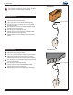
GB-AVSTOR4 Ceiling Attachment The ceiling box must be secured using the Quick Locks and 1/16˝ braided cables (supplied). Wood Stud Wood Stud Ceiling Determine the mounting location. ®® Use a 1/8” drill bit to pre-drill the mounting holes. ¯¯ Secure the four (4) ¼” eye lag screws to the wood °° ±± ²² ³³ Eye Lag Screw stud in the ceiling. Run the open end of the 1/16˝ braided cable through the hole in an eye lag screw. Run the open end through the loop.
GB-AVSTOR4 Truss Ceiling Loop the braided cable around the truss. ®® Run the open end 1/16˝ braided cable through the Ceiling Truss loop. ¯¯ Pull the open end down until the °° /16˝ braided cable tightens around the truss. Repeat steps 1-3 for the remaining three mounting points. Page 8 1 Visit the Premier Mounts website at www.mounts.
GB-AVSTOR4 Quick Lock Operation Step 1 Cable Output Please follow the steps below in numerical order , and to correctly install the Quick Lock Cable Kit. , Cable Input Release Pin To release or relieve tension on the 1/16˝ braided cable, slide the release pin to disengage. /16˝ Braided Cable 1 Release Pin Mounting Hole /16˝ Braided Cable 1 Release Pin Mounting Hole Installation Instructions Visit the Premier Mounts website at www.mounts.
GB-AVSTOR4 Step 2 Ceiling Framework It is recommended that the following steps be performed by two people. Lift the ceiling box from the exposed ceiling framework until the ceiling box’s outer lip rests against the bottom of the ceiling framework (Figure 1). ®® Adjust the /16˝ braided cable tension, but do not 1 overtighten.
GB-AVSTOR4 Mounting Tray Installation For ease of installation, the mounting tray comes packaged in a separate box within the master carton. Installers may pre-wire the mounting tray prior to the GB-AVSTOR4 ceiling box installation. Zip ties (included), small screws and flat washers are strongly recommended to hold all equipment in place. Attaching Equipment to the Tray Place your electronic components onto the mounting tray.
GB-AVSTOR4 Securing the Lid Step 1 Re-attach the ceiling box lid to the ceiling box. ®® Swing the ceiling box lid up into place. Step 2 Hold the lid in place. ®® Use a key (supplied) to lock the lid in place. ¯¯ Do not release the ceiling box lid until you are sure that the lock has been engaged and the lid is secure. Page 12 Visit the Premier Mounts website at www.mounts.
GB-AVSTOR4 Technical Specifications All measurements are in inches [mm]. 546.10 21.50 606.43 23.88 76.20 3.00 128.21 5.05 355.60 14.00 304.80 12.00 76.20 3.00 1.21 .048 27.98 1.10 553.47 21.79 114.30 4.50 286.51 11.28 Installation Instructions Visit the Premier Mounts website at www.mounts.
GB-AVSTOR4 Warranty PREMIER MOUNTS LIMITED LIFETIME WARRANTY What and Who is Covered by this Limited Warranty and for How Long Premier Mounts warrants this product to be free from defects in material and workmanship for the lifetime of the original owner of this product. The limited warranty is valid only for the original purchaser of the product. What Premier Mounts Will Do At the sole option of Premier Mounts, Premier Mounts will repair or replace any product or product part that is defective.