INSTALLATION INSTRUCTIONS VPM VESA Pole Mount NORTH AMERICA 1321 S. State College Boulevard Fullerton, CA 92831 USA USA and Canada Phone: 1.800.368.9700 Fax: 1.800.832.4888 Other Locations Phone: (001).714.632.7100 Fax: (001).714.632.
VPM Contents Weight Limit............................................................................................................................................................... 2 Warning Statements.................................................................................................................................................. 2 Installation Tools...........................................................................................................................................
VPM Installation Tools The following tool may be required depending on your installation. Phillips Tip Screwdriver Parts List Make sure none of the Premier Mounts parts are missing and/or damaged before beginning installation. If there are, stop the installation and call Premier Mounts at (800) 368-9700.
VPM Parts List (cont’d) Mounting Hardware Lock-It™ Security Hardware Pack Your mount comes with the option of using Lock-It™ Security Screws. Simply replace any of the Phillips head screws with the corresponding sized Lock-It™ Security Screws and tighten using the included Allen wrench. When you see the graphics below associated with a step, you have the option of using the standard mounting hardware or the Lock-It Security hardware.
VPM Features The VPM VESA Pole Mount packs many features that make it one of the best mounts for flat-panels up to 32”. Its attachment head uses a 100 x 100mm VESA mounting pattern to fit a majority of flat-panels (from 75 x 75mm to 200 x 200mm when combined with the optional adapter plate). For the optimal viewing angle, adjust the mount using its Radial Glide® feature, which offers up to 12° (22° with optional tilt adapters) of smooth adjustment in any direction.
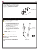
VPM Opening the Collar Clasp Remove the M8 x 40mm hex screws from the sides of the VPM to open the collar clasp and begin installation. Proceed to the “Installing the Fixed Tilt Adapters (Optional)” section.
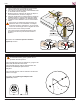
VPM Selecting the Mounting Hardware 1) Insert a small straw or toothpick into the threaded inserts found on the back of the flat-panel. 2) Use a pencil to mark the depth of the threaded insert on the small straw or toothpick. 3) Mark the straw or toothpick 1/8” above the depth of the threaded insert, as shown in Figure 1. 4) Insert the small straw or toothpick into the remaining threaded inserts to compare and verify their depth using the straw or toothpick’s 1/8” allowance mark.
VPM Installing the Adapter Plate (Optional) What is the VESA pattern on your flat-panel? • If 75 x 75mm or 200 x 200mm, proceed to the 75 x 75mm or 200 x 200mm section. • If 200 x 100mm, go to the 200 x 100mm section on page 9. • If 100 x 100mm, go to the “Attaching the Flat-Panel to the VPM Mount” section on page 10. The adapter plate has a 100mm x 100mm VESA pattern, but that is only for attaching the plate to the attachment head of the VPM.
VPM Installing the Adapter Plate (cont’d) 200 x 100mm Optional fixed tilt adapters not shown. If you have a recessed mounting pattern, use the universal spacers to compensate for the indentation. Attach the VESA Adapter Plate to the back of the flat panel using six (6) M4 flat head screws (Figure 1). See Figure 2 for a clearer view of the 200mm x 100mm pattern (marked B).
VPM Attaching the Flat-Panel to the VPM Mount Choose one of the following options. Drawings not to scale. Optional fixed tilt adapters not shown. No Fixed Tilt Adapters Are you attaching the VPM directly to the flat-panel, or are you using an adapter plate? • If directly to the flat-panel, insert Flat- Panel four (4) M4 x 10mm screws through the VPM attachment head and 100 x 100mm pattern of the flat-panel (see page 14) (Figure 1).
VPM Attaching the VPM Mount to a Pole Drawings not to scale. Mounting hardware not shown. Re-insert the M8 x 40mm hex screws or insert M8 x 40mm security screws into the two halves of the VPM to clasp them around the pole at the desired position (Figure 1). At least two qualified people are needed to attach the flat-panel and VPM to a pole. If you are using a 2” pipe, replace the M8 x 40mm hex screws with M8 x 60mm security screws (Figure 2). Proceed to the “Adjusting the VPM Mount Tension” section.
VPM Adjusting the VPM Mount Tension Your VPM ships from the factory pre-tensioned. However, you can fine-tune adjust the amount of pressure required to move the attachment head of the VPM. Use the enclosed Allen wrench to adjust the tension by loosening or tightening the M10 set screws on each side of the VPM. Do not overtighten or remove the set screws. M10 Set Screw Installing Multiple VPMs (Optional) You can attach multiple VPM mounts to a pole, such as for back-to-back flat-panel installations.
VPM Technical Specifications All measurements are in inches [millimeters]. .104 2.64 12° 12° 4.56 115.87 3.95 100.23 3.94 100 12° 2.89 73.50 4.79 121.56 3.94 100 12° Ø .18 4.50 10° A 4.56 115.87 A Attachment Head Mounting Pattern A: 100 x 100mm VESA pattern A A C B C B D E D B E Adapter Plate Mounting Patterns B. 200 x 100mm VESA pattern (M4 Phillips flat head screws only) C. 200 x 200mm VESA pattern If an M4 or M5 is to be used, a M4 or M5 washer must also be used.
VPM Warranty PREMIER MOUNTS LIMITED LIFETIME WARRANTY What and Who is Covered by this Limited Warranty and for How Long Premier Mounts warrants this product to be free from defects in material and workmanship for the lifetime of the original owner of this product. The limited warranty is valid only for the original purchaser of the product. What Premier Mounts Will Do At the sole option of Premier Mounts, Premier Mounts will repair or replace any product or product part that is defective.