USE AND CARE MANUAL AND INSTALLATION INSTRUCTIONS GAS RANGE Important Safety Instructions Inside front cover General Safety Precautions 1-2 Use and Care Surface Cooking Griddle (Optional on Some Models) Using your Oven Using your Broiler Operating your Range During an Electrical Power Failure Clock and Timer (Some Models) Care and Cleaning Before you Start Installing 3 4 5-6 7 8 9 10-12 13 Installation Backguard Installation Clearances and Location Anti-Tip Bracket Installation Connecting the Range t
IMPORTANT SAFETY INSTRUCTIONS WARNING: If the information in this manual is not followed exactly, a fire or explosion may result, causing property damage, personal injury or death. To reduce the risk of the appliance tipping, it must be secured by a properly installed anti-tip device.
GENERAL SAFETY PRECAUTIONS 15. DO NOT HEAT UNOPENED CONTAINERS OR FOOD ON SURFACE BURNERS OR IN THE OVEN. Buildup of pr essur e may cause the container to bur st and r esult in ser ious per sonal har m and/or damage to the range. 16. ALUMINUM FOIL WHEN USED IMPROPERLY IS A CAUSE OF MANY RANGE PROBLEMS. See the oven and broiler sections of this book for instructions for proper use. 17. GREASE IS FLAMMABLE AND SHOULD BE HANDLED CAREFULLY.
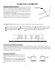
SURFACE COOKING BURNER LIGHTING SOURCE The burners on your range need an electrical source to ignite the burners. The electricity required to light the burners may come from an electrical outlet or from a battery power pack. Ranges without a power cord have a battery power pack located in the lower right corner of the range. In either case your new range is equipped with automatic ignition top burners. Each burner can be controlled to provide heat from the highest “full on” to the very low “keep warm”.
USING YOUR OVEN PILOT To use your oven, push and rotate the oven control counterclockwise to the “PILOT” or “LITE” position. Once in the “PILOT” or “LITE” position, push in on the knob as far as possible and hold for 10 sec. After holding the control knob in for 10 sec. release the oven knob. The pilot flame will remain lit. Open the oven door. When you push in and rotate the oven control knob to the desired position (temp.
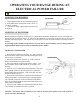
OPERATING YOUR RANGE DURING AN ELECTRICAL POWER FAILURE WARNING: USE EXTREME CAUTION WHEN LIGHTING BURNERS THIS WAY. LIGHTING TOP BURNERS TOP BURNER 1. Hold a lighted match to the desired burner head. 2. Push and turn the control knob to the “LITE” or “START” position. 3. After burner lights, adjust flame to desired size as required. LIGHTING OVEN BURNER Before attempting to light the oven burner, it is important to determine whether the oven in your range will operate during an electrical outage.
CLOCK AND TIMER (Optional on Some Models) ELECTRONIC CLOCK AND TIMER TO SET TIME OF DAY: Depr ess “CLOCK” button (a tone will sound). Depr ess “UP” button to set the time up, or depress “DOWN” button to set the time down. Tapping the “UP” OR “DOWN” button will increase or decrease the time by 1 minute. Holding in the “UP” or “DOWN” button will increase or decrease the time in 10 minute intervals.
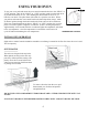
CARE AND CLEANING CLEANING BROILER PAN (if equipped): After broiling, remove the broiler pan and tray after allowing them to cool. Wash in warm, soapy water. * BROILER PAN AND TRAY MUST BE IN PLACE FOR ANY COOKING OPERATION. Slide out to remove Push up under center and roll out DO NOT USE STEEL WOOL PADS, COMMERCIAL OVEN CLEANER, SILICONE OVEN SPRAYS, COARSE PADS OR COARSE BRUSHES ON THE BROILER CARRIAGE. CLEANING TOP BURNERS Burners may be wiped off without removing from the range.
13
INSTALLATION INSTRUCTIONS PORCELAIN BACKGUARD INSTALLATION 1. Remove range main top. See Page 11. 2. Position backguard down over flue box and onto the range main sides. 3. Attach backguard to range main sides with (2) (A) bolts and (2) (B) nuts each side. 4. Assemble backguard and top edge of the flue box with (2) (A) bolts and (2) (B) nuts. 5. If backguard has a clock, connect plug from backguard to plug from back of range. 6. Replace range main top. THERMOPLASTIC END CAP BACKGUARD INSTALLATION 1.
PORCELAIN BACKGUARD MAIN TOP BACKGUARD FASTENERS REQUIRED A- B- #10-24 X 3/8” Phillips Truss Hd bolt #10-24 Hex Keps Nut B A A B B A BACKGUARD THERMOPLASTIC END CAP BACKGUARD FASTENERS REQUIRED A#8 X 1/2” Phillips Countersink Hd screw A C C#10-24 X 3/8” Phillips Truss Hd bolt MAIN TOP B B- D- #10-24 X .
INSTALLATION INSTRUCTIONS MAXIMUM AND MINIMUM CLEARANCES The sides of the range can be flush to combustible material below the cooking top. The back of the range can be flush to combustible material. A minimum clearance of 5 inches is required between the range and combustible construction extending from the cooking surface to 18 inches above the level of the cooking surface.
INSTALLATION INSTRUCTIONS ANTI-TIP BRACKET INSTALLATION WARNING The anti-tip bracket is installed to prevent the range from tipping forward as the result of excessive downward pressure on the open end of the oven door. All ranges are required to have an approved anti-tip bracket installed. The anti-tip bracket is packed in the oven section of the range. If you did not receive an anti-tip bracket with you purchase, call 1-800-858-5844. A child or adult can tip the range and be killed.
INSTALLATION INSTRUCTIONS CONNECTING THE RANGE TO GAS The installation of this gas range must conform with the local codes, or in the absence of local codes, with the National Fuel Gas Code, ANSI Z223.1/NFPA 54 “Latest Edition” in the U.S.A. or in Canada, the Natural Gas and Propane Installation Code, CSA B149.1.
INSTALLATION INSTRUCTIONS WARNING: DO NOT USE A FLAME TO CHECK FOR GAS LEAKS TESTING FOR GAS LEAKS Before turning on the gas, be sure that all range valves are in the “OFF” position. Turn on the gas and check each joint or connection with a soap and water solution, including the inlet and outlet sides of the regulator. Never test for leaks with a lighted match or open flame.
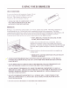
INSTALLATION INSTRUCTIONS POWERING CORDLESS RANGES (SOME MODELS) It is not necessary to connect your range to a plug-in outlet in your home. The burner ignition comes from a DC source (battery power pack). INSTALLING THE DC POWER PACK (8) AA Alkaline Batteries Before any of the burners can be lighted, it is necessary to locate the power pack that is located in the range oven section. The power pack requires (8) AA size batteries. It is recommended that a good quality Alkaline Battery be used.
INSTALLATION INSTRUCTIONS TO LIGHT TOP PILOTS (Standing Pilot Canadian Model Ranges Only) 1. Be sure the surface burner control knobs are in the “OFF” position. 2. Remove the grates and tray inserts (if any) and remove the cook top. See Page 11. 3. Locate the pilot ports and light each of them with a match. Replace the cook top, tray inserts (if any), and grates. NOTE: PILOT SHOULD BE 3/8” HIGH. IF THE PILOT IS TOO HIGH OR LOW, YOU CAN ADJUST IN THE FOLLOWING MANNER: 1. Locate the pilot adjustment screw.
CONVERTING RANGE FROM NATURAL GAS TO PROPANE GAS IMPORTANT: READ PRIOR TO STARTING THE CONVERSION PROCESS: Because your r ange may be fitted with one of three different types of oven systems, it is necessary to determine which system the range employs in order to be successful making the range conversion. These instructions provide two different methods for converting the range from Natural Gas to Propane Gas, Method A or Method B.
CONVERTING RANGE FROM NATURAL GAS TO PROPANE GAS STEP 3 METHOD A Conver t the Range Oven ther mostat. The oven thermostat control is at the center front of the range located behind the oven control knob and control panel. Locate the brass propane conversion screw the oven thermostat as shown in Fig. 2 This screw can be accessed through a hole in the control panel. 1. Turn the conversion screw clockwise until seated tight into the oven thermostat control. 2.
CONVERTING RANGE FROM NATURAL GAS TO PROPANE GAS STEP 4 METHOD A or B Conver t Oven PIN Burner: The oven burner orifice is located beneath the inlet to the oven burner at the lower rear NATURAL GAS portion of the broiler section. See Fig. 5 Using a 1/2” wrench turn the orifice hood clockwise until it is snug. Warning: Do not over-tighten the orifice hood. ORIFICE HOOD LP GAS Fig.
CONVERTING RANGE FROM PROPANE GAS TO NATURAL GAS IMPORTANT: READ PRIOR TO STARTING THE CONVERSION PROCESS: Because your r ange may be fitted with one of three different types of oven systems, it is necessary to determine which system the range employs in order to be successful making the range conversion. These instructions provide two different methods for converting the range from Propane Gas to Natural Gas, Method A or Method B.
CONVERTING RANGE FROM PROPANE GAS TO NATURAL GAS STEP 3 METHOD A Conver t the Range Oven ther mostat. The oven thermostat control is at the center front of the range located behind the oven control knob and control panel. Locate the brass gas conversion screw on the right side of the oven thermostat as shown in Fig. 4 This screw can be accessed through a hole in the control panel. 1. Turn the conversion screw counter-clockwise 360 degrees, one full turn. 2.
INSTALLATION INSTRUCTIONS CHECK SURFACE BURNER IGNITION Simultaneously push in and turn a top burner knob to the LITE or START position. On Electric Spark Ignition Models, you will hear a clicking sound indicating the proper operation of the spark module. Once the air has been purged from the supply lines, the burner will light. Rotate the knob out of the LITE or START position after the burner lights. Try each burner in succession until all burners have been checked.
INSTALLATION INSTRUCTIONS ADJUST AIR SHUTTERS, IF NECESSARY AIR SHUTTER TOP BURNERS: The air shutter adjustment for each top burner is located at the Open end of the top burner venturi tube and rests on the orifice hood of the top burner valve. Should the air shutter need adjusting, slide the air shutter to allow more or less air into the burner flame as needed.
WIRING DIAGRAMS SUPPLY CORD 120V AC 15 AMPS 12VDC (8) AA BATTERIES HOT SURFACE IGNITION SYSTEM BATTERY IGNITION SYSTEM SUPPLY CORD 120V AC 15 AMPS SPARK/THERMOCOUPLE IGNITION SYSTEM 29
BEFORE YOU CALL FOR SERVICE Before you call for service, review this list. It may save you time and expense. This list includes common occurrences that are not the result of defective workmanship or materials in this appliances. Find your problem here Possible cause How to fix it Range power cord is disconnected from the outlet. Be sure power cord is plugged into grounded outlet. Electrical power outage. Burners can be lit manually.
BEFORE YOU CALL FOR SERVICE Find your problems here Possible cause How to fix it continued: Flame is orange. Dust particles in main line. Allow burner to operate for a few minutes until flame turns blue. Make sure temperature control is set at the desired temperature. Improper air shutter adjustment. See Page 28 for proper burner air shutter adjustment. House fuse has blown or circuit breaker has tripped. Check/reset circuit breaker and/or replace fuse. Electrical power outage.
BEFORE YOU CALL FOR SERVICE Find your problems here Possible cause How to fix it Nuisance sparking while oven is in operation. Improperly grounded or reversed polarity electrical outlet. Have outlet corrected by a qualified electrician. Smoke or odor on initial oven operation. This is normal. This will stop after the range has been heated the first time. Persistent smoke or odor. Range improperly converted. Correct conversion by following instructions on Pages 22-26 in this manual.
Dear Consumer: Your range will give you years of satisfactory service and pleasure when properly cared for and used. Producing an efficient range that conserves energy requires a considerable investment of time, effort & money. Your range is engineered to surpass all performance and safety requirements. However, safety is also YOUR responsibility through proper use and care. With this in mind, it is important that you read this booklet.