
Installation Instructions

INSTALLATION INSTRUCTIONS
ANTI-TIP BRACKET INSTALLATION
NOTICE: Parts supplied are for wood, concrete or ceramic tile floors. The plastic anchors are for mounting
to concrete or ceramic floors or walls. Contact a qualified floor covering installer for the best procedure for
drilling mounting holes through your type of floor covering.
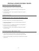
WARNING
A child or adult can tip the range and be killed.
Install the anti-tip device to the floor or the wall of the structure.
Engage the range to the anti-tip device that is fastened to the
wall or the floor.
Re-engage the anti-tip device if the range is moved.
Failure to do so can result in death or serious burns to children
or adults.
The anti-tip bracket is installed to prevent the range
from tipping forward as the result of excessive down-
ward pressure on the open end of the oven door. All
ranges are required to have an approved anti-tip
bracket installed. The anti-tip bracket is packed in the
oven section of the range.
If you did not receive an anti-tip bracket with you
purchase, call 1-800-858-5844.
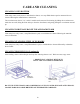
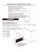
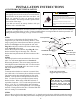
STEP 1
It is necessary to determine the final location of the
range before you can locate the anti-tip bracket. If the
range is going to be located between cabinets, place the
bracket so that Edge A sits flat against the rear wall.
Edge B should just touch the side of the cabinet sitting
to the right side of the range.
If there are no adjacent cabinets, align Edge B of the
bracket with the edge of the range side. After the
bracket has been placed mark the hole locations with a
marker.
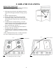
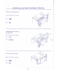
STEP 2
The anti-tip bracket can be attached to the floor or the
wall. For wall mount application use Location C.
When using location C, the screws must penetrate the
wall sill plate located within the wall. For floor mount
application use Location D or E. One screw on each
side of the bracket is sufficient.
STEP 3
To mount anchor bracket to concrete or ceramic floor,
use a drill with a 3/16”masonry bit to drill the two holes.
Tap plastic anchor into mounting holes in floor with
hammer. Line up holes in anti-tip bracket to holes in
floor. Use the two screws provided to fasten anti-tip
bracket to floor. When using a Hilti DX-460 tool or
equivalent, locate the 3 (X’s) on the anti-tip bracket and
drive a 1-1/4” X 1/4” pin through the anti-tip bracket.
To properly set the pin, it must penetrate 1-1/4” through
the floor covering and into the floor. With the Hilti DX-
460 a #3 setting is recommended.
Edge A
Edge B
Location C
Location D
Anti-Tip Bracket
Anti-Tip Bracket
Screw must pene-
trate solid wood.
Wall Sill Plate
Location E
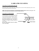
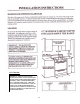
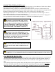
STEP 4
Unscrew the rear leg levelers approximately 1/2” so that the rear leg levelers will slide in under the anti-tip
bracket. Slide range into the final position after completing the gas and electrical connections to the range.
WARNING: IF RANGE IS
EVER MOVED TO A DIFFER-
ENT LOCATION, THE ANTI-TIP
BRACKET MUST ALSO BE
MOVED AND INSTALLED WITH
THE RANGE.
17
NOTE: The bracket should
engage the right rear leg leveler.