FROM I ACE COMPUTERS RMA PHONE NO. © 518 E6238318+6230568 Apr. 15 1998 11:13AM P2 Manual Rev: 1.0 Release Dae: March 1998 CE FCC-B Radio Frequency Interference Statement This equipment has been tasted and found to comply with the Li wits for a class B digital device. pursuant to part J5 of the FCC rules. These limits are designed to provide reasonable protection against harmful interference when the equipment is operated in 2 commercial environment.
FRI 1 ROE COMPUTERS RMA PHONE NO. @ S10 623B818+62305668 Apr. 1% 1958 11:113/M F3 Edition March 1998 Copyright Notice The material in this document is the intellectual property of MICRO STAR INTERNATIONAL. We take every care in the preparation of this document, but no guarantee is given as to the correctness of its contents. Our products are under continual impoverishment and we reserve the right to make changes without notice.
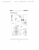
FRY © ACME COMPUTERS RMA PHONE NO. | S18 6235818+6230568 Fer. 15 1998 11:14AM P4 Table of Contents Chapter 1: Introduction 1-1 Ma inboard Features 12 Ma inboard LayOutesesssmssassras referees 15 Chapter 2: Hardware Installation 2-1 Central Processing Unit: CPU. 2-1 CPU Installation Procedures--22 CPU Core Speed Derivation Procedure-— 2.6 CPU Speed moo moo 2-17 Fan Power Connectors: CPUFAL/SYSFAL/ PARSIFAL-18 Clear COS Jumper: KIRIBATI--2.19 Memory Institutionalizes 2-20 Memory Bank Configuration.
FROM 1 ACHE COMPUTERS RMA PHONE NO 1513 623201B-6232568 Aer. 15 1998 11:14AM PS The Main 3.3 Standard COS 3.8 BIOS Features Setup---== 3.8 Chip set Features ame serrnenrenrreeeaes 313 Power Management —— 3.16 PNP/PC] Configuration Setup 3.23 Load BIOS/Setup Defaultger-m-meresr-smr 3.26 Special Features Setuperessresem=er ro 327 Integrated 3.
COMPUTERS RMA PHONE NO. © S518 6233818+6230588 Rpr. 15 1998 Pe ATX 20-pin Power Connector; JPW1-- 227 Remote Power On/Off Switch: WORMS--2.28 UDA Infrared Module Connector: (RI --e2.2% Serial Port Connectors: COM A & COM B--2-30 Parallel Port Connector: 2-31 Keyboard and Mouse Connector: JKBMS1---vevenmareenn 2:32 USB Connector: USB wamsunsrmreue.
ACME COMPUTERS RMA PHONE NO. © T1@ fpr, 1S 1958 11:15AM P7 CHAPTER 1 INTRODUCTION Chapter 1 INTRODUCTION The ATX BX] ma inboard 1s 8 high-performance personal computer ma inboard based on the Pentium® {1 processor. The Pentium® II processor supports MMX™ (Multimedia Extension) technology. The ma inboard uses the highly integrate (nisl® 82443BX AGP chip set to support the CHISINAU and Green standards, and ta provide the Hostage bridge.
FRI ACHE COMPUTERS RMA PHONE NO. ! 51D £233016-623588 Apr. CHAPTER 1 INTRODUCTION 1.1 Ma inboard Features cru # Slot 1 for Pentium® If processor. Supports 233MHz, 266MHz, 300MHz, 333MHz, 400MHz, and faster. ® Collaborationist 84, xd.5, x5, x5.5, x6 and higher Switching Voltage Regulator & On-board switching mode DC-DC Step Down Regulator # Conforms to Intel® VRM ver 8.2 specifications # Over.Voltage and Over-Current protection Chip set ® AGP chip set. Clock Generator ® 56.
CHAPTER 1 INTRODUCTION On-Board IDE ® An IDE controller on the Intel® 82371EB PCI chip set provides IDE HDD/ CD-ROM with PIO. Bus Master and Ultra DMA/33 operation modes. & Can connect vp to four IDE devices On-Board Peripherals ® On-Board Peripherals include: 1 floppy port supports 2 FDD with 360K, 720K, 1.2M, 1 44M and megabytes 2 serial ports {COMA + COMB) 1 espalier! port supports SPP/EPP/BCE made -USB pores 1 'DA connector for Fast IDA.
FROM 1 ACHE COMPUTERS FMA PHONE MNO. © 518 6235018+6232588 Fpr. 15 1998 11:18AM P1 CHAPTER 1 INTRODUCTION 1.
1 ACHE COMPUTERS RMA PHONE NO. 518 623386232588 fpr. 15 1998 P2 CHAPTER 2 HARDWARE INSTALLATION Chapter 2 HARDWARE INSTALLATION 2.1 Central Processing Unit: CPU The ma inboard operatic with Intel? Pentium® IU processor. The ma inboard scud a CPU Slot called Slot 1 for easy CPU installation. To settee proper sped for the CEU, you should first check your ma inboard. There are two kinds of ma inboard: CPU Plug & Play ma inboard & Standard ma inboard.
FROM 1 ACHY COMPUTERS RMA PHONE MO. © 512 6230G1E+623US88 Fpr. 1S 1990 11:196M P3 CHAPTER 2 HARDWARE INSTALLATION 2.1-1 CPU Installation Procedures Different kinds of Pentium® I processor that is currently used: the OEM version, the Boxed version, and Electron. OEM Pentium? IX Processor has no Heat Sink, Pag and Heat Sink Support, the Boxed Pentium® I{ Processor is provided with Feat Sink w/ fan and Heat Sink Support, while the Celeron™ processor is 4 plane processor card without cover or heat sink. A.
FRO ACHE COMPUTERS RMA PHONE ND. © S18 6236018+6232580 Apr. 15 1998 11:28AM P4 CHAPTER 2 HARDWARE INSTALLATION *Heat Sink Support Pin (SPIN} Plastic pins assertive through the HBASE to secure it to the ma inboard (2 required per Assembly). *Heat Sink Support Top Bar (STOP) Plastic bar that clips onto the HBASE through the fins on the ATX heat sink. ++Heat Sink w/ fan Heat Sink that can be attached to the Pentium® {1 processor with meal clip. Nate: * Provided by Mortarboard.
Fra BATHMAT COMPUTERS FMR PHONE NI. 1 2 6233018-5232588 fpr. 15 19S8 11:28AM PS CHAPTER 2 HARDWARE INSTALLATION Step §: Install the Heat Sink with Fan 10 the Processor, Push down the metal clips, so that they are in line with the back of the Heat Sta, Be careful, so as not detach the metal clips from the Heat Sink. Heat Sink w/ Fan The arrow should be pointing down. Ip case the metal clips ace detached from the Heat Sink, re-attach them, Look for the arrow on the metal clip.
FROM © ACHE COMPUTERS RMA PHONE MO. ! S19 6232819+6232588 Fpr. 1S 1998 11:21AM Po CHAPTER 2 HARDWARE INSTALLATION Step 6: Install the Processor. Unlock the Assessor by pushing in the Processor Locks. Insert the Processor like inserting 2 PCT ot an 184 card. Step 7: Lock the Processor Locks.
FROM : ACHE COMPUTERS RIA PHONE NO. @ S18 6239818+6233568 Apr. 15 1998 11:21AM P?7 CHAPTER 2 HARDWARE INSTALLATION Step 8: Install the Heat Sink Support Top Bar Push the Heat Sink Support Top Bar 10 the Heat Sink Support Base, Until you hear a “click” sand. Check for 2 perfect fit, Heat sink Support Top Bar The installation is now complete.
PROF ACME COMPUTERS RMA PHONE NO. © S10 6238C18+62732586 Apr. 15 1998 11:22AM FB CHAPTER 2 HARDWARE INSTALLATION Step 3: Install the Heat Sink 10 the Processor. Push down the plastic clips, so that they are in line with the hole on the processor. check for perfect fit. Step 4: Insert the Processor in Insert the Processor like inserting a PCI or an ISA card.
FRO 0 ACME COMPUTERS FMA HOKE MJ. © 510 p23BE1E-6232588 Apr. 15 1998 112248 PY CHAPTER 2 HARDWARE INSTALLATION 2.1-2 CPU Core Speed Derivation Procedure I “The DIP Switch SW: (1,2, 3, and 4) is used to set the Core/Bus (Fraction) rac of the CPU. The actual core speed of the CPL 15 the Host Clack Frequency multiplied by the Core/Bus taro. For example r PL Clock = CMH. Coreligionist = 35 then Prospected = Host Clock x Coyotes ratio = 66M» 3.5 = 233MHr.
FROM 1 ACHE COMPUTERS RMA PHONE NO. © 519 6233818+6238588 Apr. 15 1958 11:23AM Pid CHAPTER 2 HARDWARE INSTALLATION 2.1.3 CPU Speed Setting To adjust the speed of the CPU, vou must know the specification of your CPU (sways ask the vendor for CPU specification). a. 66MHz CPU Bos Frequency Table 2.1 200 ~ 333MHz (ntel® Pentium® Nl processor b. 100MEz CPU Bus Frequency Table 2.
FRY © ACHE COMPUTERS RMA PHONE NI. © S18 6238518+6232588 Fer. 15 1998 11:24AM P11 CHAPTER 2 HARDWARE INSTALLATION 2.1-4 Fan Power Connectors: CPUFAN1/PSFANI/SYSFAN1 These connectors support system cooling fan with +12V. It supports three pin head connector. Her connecting the quite ta the connector, always {uke 1:0ts that the red wire is the positive and should be connected to the +12V. the black wire is Ground and should be connected to GND.
FRI ACHE COMPUTERS RMA PHONE NO. © S18 R2Z3SE18+6228508 Apr, 15 1998 11:24AM P12 CHAPTER 2 HARDWARE INSTALLATION 2.2 Clear COS Jumper: BAT A battery must be used fa retain the ma inboard configuration wm COS RAM. If you use the on-board battery, you must short 1-2 pins of TAT to keep the COS data. Cl oar Data Note: You can clear COS by shorting 2.3 pin, while the system is off. Then, return to 1-2 pin position. Avoid clearing the COS while the system is on; it will damage the ma inboard.
FRO | ACHE COMPUTERS RMA PHONE NO. © S18 6238518+6238588 Apr. 15 1998 11:25AM P13 CHAPTER 2 HARDWARE INSTALLATION 2.3-2 Memory Installation Procedures A. How to install a DIM Module hi i Double Sided DIM |. The DIM slot has a two Notch Key “VOLT und DRAM”, so the DIM emery module can only fit in one direction 2. Insert the DIM memory module vertically into the DIM sot ‘Then push it in sf n._. anon wort 2, Tie plastic clip at the side of the DIM slot will automatically Pp y close. Note: You car only use & 3.
FRM © ROVE COMMUTERS RMA PHONE MO. 1 S10 623HE18+623LSB8 Apr. 15 1998 11:26AM P16 CHAPTER 2 HARDWARE INSTALLATION 2.
FROM © ACE COMPUTERS RMA PHONE NO. © 518 Fer. 15 1998 11:27aM F18 CHAPTER 2 HARDWARE INSTALLATION 2.5 Floppy Disk Connector: FDD “The ma inboard also provides standard floppy disk connector FDC that supports 360K, 720K, 1.2M, 1.44M znd 288M floppy disk types, This connector support the provided floppy drive ribbon cables. FOO 2.
FROM : ACHE COMPUTERS RMA PHONE NO. 1 518 AZ3BE10+6230563 Ppr. 15 1996 11:28AM P19 CHAPTER 2 HARDWARE INSTALLATION 2.6 Hard Disk Connectors: DIET & IDES The ma inboard has 32-bit Enhanced PCI IDE Controller that provides PIO mode 0-4, Bus Master, and Lira DMA/Z3 function. Jt has two HDD connectors IDE] {primary} and IDES {secondary}. You can connect up to four hard disk drives, CD-ROM.
FRO 1 ACHE COMPUTERS RIA PHONE M0. © S13 6233010+6232568 Fer. 15 1998 11:26AM P20 CHAPTER 2 HARDWARE INSTALLATION 2.7 Power Supply 2.7.1 ATX 20-pin Power Connector: JP “This connector supports the power bunion on-board. Using the ATX power supply. functions such as Modem Ring Wake-Up and Soft Power Off are supported by this ma inboard. This POWER CORNCOB SUPPORTS TUNISIAN POWER on function which means that system will boot up instantly when the power couturier is inverted on tie board.
FROM © ACHY COMPUTERS FR PHONE MO. © 518 6238018+6278588 Fpr. CHAPTER 2 HARDWARE INSTALLATION 27.2 Remote Power On/Off Switch: WORMS Contest to a 2-pin push button switch, During OFF state, press once and the system ms on. Daring Onstage, push once und the system goes to sleep mode: pushing it more than d seconds will change its status farm ON to OFF. [f you want to change the stoup, you could go to the BIOS Power Management Setup.
FRO © ACHE COMPUTERS FMA PHONE NO. © S10 £6235918+6230568 fpr. 1S 1998 111256 FI2 CHAPTER 2 HARDWARE INSTALLATION 2.8 Ir DA Infrared Module Connector: IR1 The ma inboard provides ove §-pin infrared (IRL connector for [R modicums. This connector is for optional wireless transmitting and receiving infrared module. You must configure the setting through the BIOS setup to use the IR function. FIR and Consumes [R are reserved functions.
FROM 1 ACHE COMPUTERS RMA PHONE MO. © S18 6233010-6232568 Rpr. 15 1998 11:38AM P23 CHAPTER 2 HARDWARE INSTALLATION 2.9 Serial Port Connectors: COMA & COMB The ma inboard has two 9-pin male DIN connectors for serial ports COM A and COM B. These two ports arc [6550A Thing speed communication ports (hat send/receive 16 bytes FIFO. You can attach 4 mouse of « modem cable directly into these connectors.
FROM © ACHE COMPUTERS RMA PHONE NO. 1 $18 623RS1B-62RESHE Fer. 15 1998 11:30AM F24 CHARTER 2 HARDWARE INSTALLATION 2.10 Parallel Port Connector: LPT The mam board provides a 25 pin female concentric connector for LPT. A parallel port is 2 standard printer pint that oafs supports Enhanced Parallel Parterre) and Extended capabilities Parallel) Porphyritic.
FROG © ACE COMPUTERS RMA PHONE NC. © 518 A2EAEI18+623ES83 fpr. 15 1938 11:31AM F2S CHAPTER 2 HARDWARE INSTALLATION 2.11 Mouse Connector: DBMS The boardroom provides a standard mouse mini DIN connector for attaching a PS/2% mouse. You can plug a P8/2% mouse dialyzes into this connector. The connector nation and pin definition are shown below: P5/2 Mouse {6-pl Female) 2.
FROM 1 ACHE COMPUTERS RMA PHONE NO. © $10 6238818+6232588 Fer. 15 1998 11:31AM P26 CHAPTER 2 HARDWARE INSTALLATION 2.13 USB Connector: USB The maintained provides a Universalize Host Controller Interface) Universal Serial Bus root fot attaching USB devices like: keyboard, mouse and other USB devices, You can plug the USB device directly to this connector.
© ACME COMPUTERS EMA PHONE NO. © 518 6233018+8232583 fpr. CHAPTER 2 HARDWARE INSTALLATION 2.14 Power Saving Switch Connector: JG Attach a power saving switch to JG. When the switch is pressed, the system immediately goes into suspend mode. Truss any key and the system wakes up.
FROM © ACHE COMPUTERS RMA PHONE NO. © S10 6233818+6230SE0 Apr. 15 1998 11:326M P23 CHAPTER 2 HARDWARE INSTALLATION 2.15 Power Saving LED Connector: JG GLIB can be connected with LED. Thus will lit while the stern iy in suspend mode. 2.
FROM © ROME COMPUTERS RMA PHONE NO. © 519 6233218-6230S68 fpr. 15 1998 11:1330M P23 CHAPTER 2 HARDWARE INSTALLATION 2.16 Power On Mode Jumper: JP2 The ma inboard supports two kinds of system boot up: the Boole-Up by switch end the Immediate Boot-Up. With the Boot-Up by Switch, the system will boot up only when the power on switch is pressed. For Immediate Boot Up, the system will boot up instantly when the power connector is connected into the mr) Table 2.
FROM © ACHE COMPUTERS RMA PHONE ND. © S18 68238816-6230288 Rpr. 15 1998 11:330M P30 CHAPTER 2 HARDWARE INSTALLATION 2.17 SB_Link™ Card Sound Connector: SLINK “The ma inboard provides a distributed DMA connector for PCI sound curd with this feature, such as Creative® PCI 31 sound ease.
FRX © REAR COMPUTERS EMA PHONE NO. © 510 B233E10+6239588 fer. 15 1998 11:34AM F31 CHAPTER 2 HARDWARE INSTALLATION 2.18 Modem Woke Up Connector: JMDM1 The IMAM connector is for used with Modem add-on card that supports the Modem Wake Up function PIN SIGNAL 1 NC 2 GND 3 MAKEUP 4 NC 5 VSB Note: Modem eke-vp signal is active “low” Note: To he hale to use this function, you need a power supply that provide enough power for this forte.
FROM @ CHURCHMEN COMPUTERS RMA PHONE MO. © $10 6238318+6232568 Apr. 15 1996 11:34AM P32 CHAPTER 2 HARDWARE INSTALLATION 2.19 Wake-Up on LAN Connector: AWOL The WOOLITE connector is for use with LAN add-on cards that supports ‘Wake Up on LAN function Note: LAN wake-up signal 1 active “hug. Note: To be able (0 use this function, you need a prier supply that provide enough power for this feature.
FROM @ ACHE COMPUTERS RMA PHONE NJ. © S18 Fpr. 15 1939 11:34AM P33 CHAPTER 2 HARDWARE INSTALLATION 2.20 CPU Temperature Sensor: SORRY This is used to check the CPU temperature. The SORT! is a sensor that is placed near the processor heat sink.
FROM © ACME COMPUTERS RMA PHONE NO. © 518 5232818+6232% a fpr. 15 1998 11:35AM P34 CHAPTER 2 HARDWARE INSTALLATION 2.21 Chassis Intrusion Connector: JP3 This connector is connected to 2-pin connector chassis switch. If the Chassis is pane, the switch will be short. The system will record ais status. To clear the warning, you must enter the BIOS setting and clear the status.
FROM | ACHE COMPUTERS RMA PHONE NO. 0 SIU 6238818+6230558 Fer. 15 1598 11:358M P35 CHAPTER 2 HARDWARE INSTALLATION 2.22 Keyboard Power-On Enabled: JV (reserved) This is used to enable the keyboard power on feature. This drainboard supports keyboard power-on feature. The keyboard needs to have a peer supply which can provide sufficient SV standby power for both the keyboard and the ma inboard.