
Instructions / Assembly


10
A
C
C
C
7
8
8
3
4
76
BB
BB
BB
A
Fig. 13
Installation
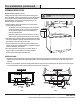
REMOVING THE ELECTRICAL KNOCK-OUT HOLE
WARNING: Always wear safety goggles and gloves during
installation.
- Choose the appropriate electrical knock-out hole to remove
for your installation type. Use the top hole (1) if your electrical
supply is in the cabinet and the back hole (2) if your electrical
supply is on the wall below the cabinet (refer to Fig. 10).
- Use a hammer and a athead screwdriver to gently punch out
the electrical knock-out hole.
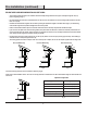
REMOVING THE VENTING HOLE
- Choose the venting hole to remove for your installation
type. Use the top hole (3) for a top venting installation
and the back hole (4) for a back venting installation.
- Carefully remove the cover (3 or 4) of the appropriate
venting hole using a at head screwdriver or needle
nose pliers (refer Fig. 11). Be careful not to leave any
debris inside the range hood (A).
- If you are venting indoors, unscrew the 2 screws
holding cover (5) in place and remove the cover as per
Fig. 12. DO NOT REMOVE ANY OTHER VENTING HOLE
COVER.
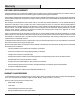
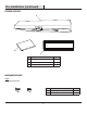
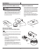
INSTALLING THE DAMPER
(SKIP THIS STEP IF YOU ARE USING INTERIOR VENTING)
NOTE:
Only install the damper if you are using a venting system that does not already
have a damper.
If this hood replaces an existing unit, the location of the air exhaust can vary
from one manufacturer to another. Ensure that the damper ts in the existing
opening before installing.
- Choose to install the damper (C) either in the top
position (3) for top venting or in the back position (4)
for back venting.
- Insert the damper (C) into the chosen hole in the range hood
(A), ensuring that the central ap (6) goes into the hole while
the two side aps (7) remain above it.
- Lift the lid (8) of the damper and screw the damper (C) to the
range hood (A) with the two short tapping screws (BB).
- Seal the damper (C) to the range hood (A) on all four sides with
duct tape.
Fig. 10
4
A
3
5
5
Fig. 11 Fig.12
A