
Instructions / Assembly


7 CONGLOMKB.COM
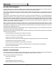
Please contact customer.service@conglomkb.com or 1-877-333-0098 for further assistance.
Pre-Installation (continued)
PLANNING INSTALLATION
Number of people required: 2 or more
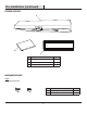
Carefully check the range hood for damage and for missing parts
prior to installation. If there is any damage or if you are missing parts,
do not proceed with the installation. Report damage and missing
parts immediately. Do not dispose of packaging before you are
satised with your new range hood.
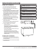
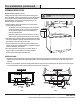
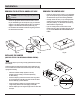
1. Before installation, measure all distances to ensure the proper
position of the range hood (A).
- The distance (1) from the cooking surface to the range hood
must be at least 458 mm (18 in). For the best performance,
do not install the range hood more than 710 mm (28 in)
above the cooking surface.
- Dimension (2) should be at least 762 mm (30 in). The range
hood should be approximately the same size as the cook top.
2. If the bottom of the cabinet (3) above the location where the range
hood is to be installed is recessed, attach appropriately sized wood
ller strips (4) on each side using wood screws.
3. Screws are provided to secure the range hood to most types of
cabinets, but consult a qualied installer to verify that the supplied
screws are suitable for your cabinets.
4. Put a thick, protective covering over your counter, cooktop, or
range to protect it from damage and dirt during installation.
Remove any hazardous objects around the area.
WARNING: Always wear safety goggles and gloves during
installation.
1
2
2
3 4
4
4
A
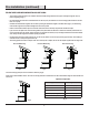
VENTING OPTIONS:
a. Determine if your existing venting system is top venting or back venting, and ensure that the openings in the cabinet or wall for the
damper and for power access are in appropriate locations and are of appropriate sizes, as per Fig. 3 if it is top vent or Fig. 4 if it is
back vent.
b. If this is a new installation, choose the venting method that suits your needs. Cut out openings for the damper and for power access
in the cabinet bottom or exterior wall, depending on the direction of venting chosen.
Fig.3 Fig.4
260
10-1/4”
260
10-1/4”
Fig. 2