
Service manual

26
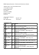
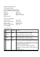
4 30 mV Mod. VR104 Adjust VR104 for 32.5V reading on the RF VTVM.
5 Ditto VR106 Adjust VR106 so that the carrier leakage at USB and LSB
becomes minimum and almost equal.
6 Mode: CW
No Mod.
VR103 Connect a SW between Pin 8 and 9 of the ACC connector.
With the SW turned on, adjust VR103 for 21W reading on the
Power meter.
7 Mode: AM
No Mod.
VR107 Adjust VR107 for 10W reading on the RF power meter.
8 Ditto VR117 Adjust VR117 so that "9" LCD just lights on.
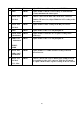
9 1 kHz, 30mV
Modulation
VR114 Adjust VR114 to obtain the 85% negative reading on the
oscilloscope.
10 1kHz, 1mV
Modulation
INDIC:
MOD
VR115 Adjust VR115 so that "9" LCD just lights on.
11 Mode: FM
1kHz, 30mV
Modulation
VR105 Adjust VR105 for +/- 3kHz deviation reading on the FM
Linear Detector.
12 Mode: CW
No Mod.
Vol. : Max
VR116 Connect a AF VTVM across a dummy load (8 Ohm) between
Pin 1 and Pin 2 of the ACC connector. With the SW turned
on, adjust VR116 for 0.4V negative reading on the AF VTVM.