Central Station Plus Owner’s Manual ™ www.presonus.
Central Station Plus 0.1 Important Safety Instructions The exclamation point within an equilateral triangle is intended to alert the user to the presence of important operating and maintenance (servicing) instructions in this manual. The lightning flash with arrowhead symbol within an equilateral triangle is intended to alert the user to the presence of uninsulated “dangerous” voltage within the product’s enclosure that may be of sufficient magnitude to constitute a risk of electric shock to humans.
Owner’s Manual Table of Contents INTRODUCTION — 1 1.0 Getting Started — 2 1.1 Connect Power — 2 1.2 Connect Input Sources — 2 1.3 Connect the CSR-1 to Your Central Station — 3 1.4 Connecting Monitor Speakers — 3 1.5 Using the Digital Input — 4 1.6 Using the Headphones and Talkback System — 5 PART II: REFERENCE — 16 5.0 Controls and Connections — 16 5.1 5.1.1 Talkback — 16 5.1.2 Headphones — 16 5.1.3 Cue/Main Select — 17 5.1.4 Meter — 17 5.1.5 Passive Speaker Control — 18 5.
iv
Owner’s Manual INTRODUCTION Thank you for purchasing the Central Station Plus, the ultimate monitoring and communications system for recording studios. The Central Station uses highgrade components to ensure optimum performance that will last a lifetime and features a purely passive signal path for ultimate sonic performance.
1 1.1 1.0 1.1 Central Station Plus Getting Started Connect Power Getting Started Connect Power Before connecting a power supply to the Central Station, ensure that the power supply meets the input-voltage requirements of the region or country where you are using it. PreSonus only supports the power supply that is shipped with your Central Station. If it does not meet your requirements, or you wish to purchase an additional power supply, please contact your local dealer or distributor. 1.
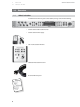
Owner’s Manual 1.3 Getting Started Connecting the CSR-1 to your Central Station 1 1.3 Connecting the CSR-1 to your Central Station 1. Connect one side of the included DB15 cable to the back of the CSR-1 and the other side to the Console connection on the back of your Central Station. Please note that the DB15 cable has a proprietary pin-out; it looks like a standard VGA cable but is wired differently. If you require a replacement cable, you will need to order it from www.PreSonus.com. 2.
1 1.5 Central Station Plus Getting Started Using the Digital Input 10. Power up your power amp or powered monitors and turn the level controls to 0 dB. 11. Press the Speaker Output A button. 12. Press the TRS 1 button in the Main Input Select section. 13. Play a stereo signal from your main input source and slowly turn the volume on the source to unity gain. You may need to consult the manufacturer of your main input source if you do not know the position of unity gain. 14.
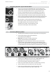
Owner’s Manual 1.6 Getting Started Using the Headphones and Talkback System 1 1.6 Using the Headphones and Talkback System 1. Turn the Phones and Mic levels fully counterclockwise. 2. Press the Phones 1 control knob so that the Cue light, rather than the Main light, is illuminated. 3. Press the TRS 1 button in the Cue Input Select section. 4. Connect a pair of headphones to the Phones 1 output. 5. Play a stereo signal from the source connected to the TRS 1 input. 6.
2 2.1 2.0 2.
Owner’s Manual 2.2 Overview Features 2 2.2 Features The Central Station features high-quality analog circuitry and digital conversion. Three sets of stereo analog inputs enable the Central Station to accept a wide variety of sources. Its S/PDIF coax and Toslink (optical) digital inputs provide up to 24-bit, 192 kHz digital-to-analog conversion, and the converters deliver over 115 dB of dynamic range. Each of the three sets of balance monitor outputs has a passive trim pot.
3 3.1 Central Station Plus Calibration Calibrating the Meter 3.0 Calibrating Your Central Station In order to create the most accurate mixing environment, it is important to calibrate each component in your system so that the metering and output levels match. 3.1 Calibrating the Meter The meters on your Central Station can (and should) be calibrated to match the meters in your DAW or on your mixer. 1. Send a 1 kHz, 0 dBu sine-wave test tone to any input on your Central Station.
Owner’s Manual Calibration Calibrating Speaker Levels 3 3.3 Aux/Phono only: Do not adjust the output level of your audio device if it is set at its optimum or maximum level. Instead, turn on your phono preamp (if necessary) and increase the Aux Input Level knob, starting from -80, until the red 0 dBVU meter just comes on (and no higher). 5. Repeat steps 1 through 3 for the secondary/cue audio sources connected to the TRS 2 and Aux inputs. 3.
3 3.3 Calibration Calibrating Speaker Levels 3.3.1 Central Station Plus Maximum Loudness Reference This method of speaker calibration references a 0 dBVU meter reading to the loudest level you want.
Owner’s Manual Calibration Calibrating Speaker Levels 3 3.3 12. Test: Play audio through Speaker A only. Without adjusting any of the Central Station’s levels, toggle Speaker A off and Speaker B on. You may hear a slight tonal variance due to the different acoustic properties of the monitoring systems but the loudness should remain the same. If the loudness varies drastically, you may wish to repeat this calibration procedure from step 1. 3.3.
3 3.3 Calibration Calibrating Speaker Levels Central Station Plus 10. If you are calibrating a monitoring system with independent subwoofer level control (such as a 2.1 or 2-way speaker system), repeat steps 4 to 9 for the subwoofer level. Repeat steps 1 through 10 for the monitoring systems connected to Speaker Outputs B and C. 11. Test: Play audio through Speaker A only. Without adjusting any of the Central Station’s levels, toggle Speaker A off and Speaker B on.
Owner’s Manual 4.0 Sample Hookup Diagrams Separate Control Room and Recording Room 4 4.1 Sample Hookup Diagrams The Central Station is an extremely flexible tool and can be used in all stages of the recording and music-production process. There are many ways to use and set up your Central Station. Here are two typical setups. 4.
4 4.1 Central Station Plus Sample Hookup Diagrams Separate Control Room and Recording Room (continued) Separate Control Room and Recording Room (continued) 4.
Owner’s Manual 4.2 Sample Hookup Diagrams Mixdown / Mastering Setup 4 4.2 Mixdown / Mastering Setup Here is a typical mixdown or mastering setup in which the Central Station’s 24-bit, 192 kHz digital-to-analog converter is being used to compare the music being created (mixed or mastered) with a commercial CD.
5 5.1 Central Station Plus Controls and Connections Front Panel Layout PART II: REFERENCE 5.0 Controls and Connections 5.1 Front Panel Layout 5.1.1 Talkback 5.1.2 •• Talkback microphone. The built-in talkback microphone is an electret condenser microphone and is positioned just below the Talkback Level knob. •• Talkback Level. Adjusts the gain level of the talkback microphone preamplifier +15 to +55 dB. •• Talk. Engages and disengages the talkback-microphone preamplifier.
Owner’s Manual 5.1.3 Controls and Connections Front Panel Layout 5 5.1 Cue/Main Select The Central Station comes equipped with separate Cue and Main signal paths. The Cue signal path includes the talkback-microphone signal and sends this signal to the recording artist via an external headphone amp or the two onboard headphone amps. The Main signal path is intended for the control room and does not include the Talkback signal. •• Cue Output Level Control.
5 5.2 Central Station Plus Controls and Connections Back Panel Layout 5.1.5 Passive Speaker Control •• Speaker Select (A, B, and C). These buttons activate stereo speaker linelevel outputs A, B, or C. Speaker Select A and B cannot be enabled at the same time. Speaker Select C can be enabled concurrently with either A or B. Because of this, Speaker C is typically used for a subwoofer. •• Speaker Trim Left/Right (A, B, and C).
Owner’s Manual 5.2.2 Controls and Connections Back Panel Layout 5 5.2 Digital Inputs (24-bit/192 kHz) Central Station automatically reads and locks to the sample rate of the incoming digital stream and can receive and lock to sample rates of 44.1, 48, 96, and 192 kHz. Both of these digital inputs are designed for the S/PDIF stereo digital format. Coaxial connectors are most commonly used for S/PDIF.
5 5.2 Central Station Plus Controls and Connections Back Panel Layout 5.2.5 Analog Inputs These inputs are for your audio sources (mixer, audio interface, CD player, etc.). Only balanced cables should be used when connecting the balanced TRS inputs of your Central Station to these devices. Because of the Central Station’s passive circuitry, using unbalanced cables can reduce the output level and can introduce noise into your system. •• TRS 1 (L/R). Left and right, line-level, balanced ¼” TRS inputs.
Owner’s Manual 5.3 Controls and Connections Central Station Remote 5 5.3 CSR-1: Central Station Remote The Central Station Remote Control (CSR-1) connects to the rear of the Central Station via a proprietary DB15 cable (included with the Central Station Plus) to control Volume, Talkback, Mute, Input Source Switching and Speaker Output Switching functions. Allowing you to keep the Central Station in your rack with your gear and use the CSR-1 on your desktop for ultimate control and flexibility.
6 6.1 Technical Information Frequently Asked Question 6.0 6.1 Central Station Plus Technical Information Frequently Asked Questions Why can’t I hear the talkback microphone? •• Only headphones with a Phones Source of “Cue” can hear the talkback microphone. •• Connect and/or calibrate your talkback microphone according to Section 1.5. •• Verify your external mic does not require phantom power. •• If you are not using an external microphone, disconnect anything connected to the XLR input.
Owner’s Manual 6.2 Technical Information Troubleshooting 6 6.2 Troubleshooting Please note that many technical issues can arise when connecting different components in a studio environment. PreSonus only provides support for issues directly related to the Central Station Studio Control Center; we do not provide support for non-PreSonus hardware and software. It may be necessary to contact the manufacturers of your other studio equipment to obtain additional technical support. Please check www.presonus.
6 6.3 Central Station Plus Technical Information Specifications 6.3 Specifications Audio Inputs TRS1 & TRS2 Type ¼” TRS Passive-Balanced Input Impedance 2-5Ω (depends on speaker load and trim) S/N Ratio >140 dB THD+N < 0.0005% (1 kHz @ 0 dBu) Frequency Response > 1 MHz Aux Type RCA Active-Unbalanced Input Impedance 8 kΩ S/N Ratio >115 dB (1 kHz @ 0 dBu, Unity gain) THD+N < 0.002% (1 kHz @ 0 dBu, Unity gain) Frequency Response 10 Hz-50 kHz, -0.
Owner’s Manual Technical Information Specifications 6 6.3 Main Type ¼” TRS Active-Balanced Output Impedance 51Ω THD+N <0.0025% Frequency Response 10 Hz-50 kHz, -0.5 dB Cue Type ¼” TRS Active-Impedance Balanced Output Impedance 51Ω THD+N < 0.003% (1 kHz @ 0 dBu) Frequency Response 10 Hz-50 kHz, -0.5 dB Gain Range -90 dB to 0 dB Dim Attenuation -16 dB (Talkback activated) Headphones Type ¼” TRS Active Stereo Maximum Output 150 mW/channel @ 60Ω load THD+N 0.
6 6.3 Central Station Plus Technical Information Specifications Input Meters Type 30-segment LED w/Peak Hold Range -48 dB to +18 dB (-66 dBfs to 0 dBfs) Accuracy Better than 0.25 dB Frequency Range 10 Hz-22 kHz Calibrate Range ±18 dB Power Supply Type External Power Input Voltage Range 12-18 VDC Power Requirements (continuous) 10W Physical Main Chassis Package Type 1U Dimensions 19 (W) X 1.75 (H) X 5.50 (D) inches Weight 5.0 lbs.
MIC LEVEL TALKBACK CUE LEVEL OUTPUT SWITCHING L L L EXTERNAL DYNAMIC L L HEADPHONE SWITCHING MIC DIM L L L INTERNAL ELECTRET EXTERNAL ENABLE SPDIF DAC DIM MONO L L R R MUTE MASTER VOLUME FOOTSWITCH REMOTE TOSLINK COAX AUX L TRS 2 L R L L L R L R L R L R L R L PHONES CUE 2 1 SPEAKER C SPEAKER B SPEAKER A MAIN OUTPUT 6.4 TRS 1 INPUT SWITCHING INPUT METERS Owner’s Manual Technical Information Block Diagram 6 6.
6 6.5 6.
Owner’s Manual 6.6 Technical Information PreSonus Limited Warranty 6 6.6 PRESONUS LIMITED WARRANTY PreSonus Audio Electronics, Inc., warrants this product to be free of defects in material and workmanship for a period of one year from the date of original retail purchase. This warranty is enforceable only by the original retail purchaser. To be protected by this warranty, the purchaser must complete and return the enclosed warranty card within 14 days of purchase.
Owner’s Manual Added bonus: PreSonus’ previously Top Secret recipe for… Jambalaya Ingredients: •• •• •• •• •• •• •• •• •• •• •• •• 5 lbs link andouille sausage 3 lbs boneless chicken 2 lbs ground beef 3 lbs onions (yellow or purple) 2 stalks of celery 1 lb bell peppers (green or red) 1 batch green onions 3 lbs rice Tony Chachere’s Cajun Seasoning 1 bottle chicken stock concentrate (or 3 cubes chicken bullion) 1 can Rotel tomotoes with chilies, diced (regular hot) Tabasco sauce Cooking Instructions: 1. 2.
Central Station Plus Owner’s Manual EMC Statement NOTE: This equipment has been tested and found to comply with the limits for a Class B digital device, pursuant to part 15 of the FCC Rules. These limits are designed to provide reasonable protection against harmful interference in a residential installation. This equipment generates, uses, and can radiate radio frequency energy and, if not installed and used in accordance with the instructions, may cause harmful interference to radio communications.