
User Manual

21
5 Aggregating Devices
5.2 Windows
Quantum-series
Owner’s Manual
5.2 Windows
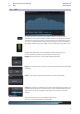
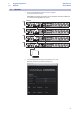
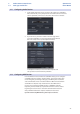
1. Connect your Quantum interfaces to your computer
and launch Universal Control.
Please Note: Your Quantum interfaces must be clocked to each other via BNC and
one unit must be designated as the master.
2. Select the Quantum interface you would like to use as the
first bank of channels and set the priority to “1.”
345678
OUT
IN
L
R
IN
OUT
IN OUT
1
2
3
4
5
6
7
8
R
-
+
12V 5A
QUANTUM
R
19-26 48kHz 11-18
15-18
96kHz
11-14
25-32 48kHz 17-24
21-24
96kHz
17-20
IN
Clock S/PDIF Main Out Line Outputs TRS Balanced Mic/Line Inputs
MIDI
Power
INOUT
345678
OUT
IN
L
R
IN
OUT
IN OUT
1
2
3
4
5
6
7
8
R
-
+
12V 5A
QUANTUM
R
19-26 48kHz 11-18
15-18
96kHz
11-14
25-32 48kHz 17-24
21-24
96kHz
17-20
IN
Clock S/PDIF Main Out Line Outputs TRS Balanced Mic/Line Inputs
MIDI
Power
INOUT
345678
OUT
IN
L
R
IN
OUT
IN OUT
1
2
3
4
5
6
7
8
R
-
+
12V 5A
QUANTUM
R
19-26 48kHz 11-18
15-18
96kHz
11-14
25-32 48kHz 17-24
21-24
96kHz
17-20
IN
Clock S/PDIF Main Out Line Outputs TRS Balanced Mic/Line Inputs
MIDI
Power
INOUT
345678
OUT
IN
L
R
IN
OUT
IN OUT
1
2
3
4
5
6
7
8
R
-
+
12V 5A
QUANTUM
R
19-26 48kHz 11-18
15-18
96kHz
11-14
25-32 48kHz 17-24
21-24
96kHz
17-20
IN
Clock S/PDIF Main Out Line Outputs TRS Balanced Mic/Line Inputs
MIDI
Power
INOUT
Computer
Quantum #1 (Master)
Quantum #2
Quantum #3
Quantum #4