StudioLive AI-Series Mixers ™ Digital Mixing System with Active Integration ™ Owner’s Manual ® www.presonus.
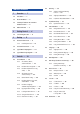
Table of Contents 1 Overview — 1 1.1 Introduction — 1 1.2 About This Manual — 2 1.3 Summary of StudioLive AI-series Mixer Hardware Features — 2 1.4 What is in the Box — 3 2 4.2 4.3 Metering — 35 4.2.1 StudioLive Fat Channel Metering Controls — 35 4.2.2 Subgroup and Main Meters — 36 4.2.3 A Quick Note About dBu and dBFS — 36 Input Channel Strip — 37 4.3.1 4.4 Input Channel Controls — 37 Aux and FX Buses — 38 4.4.1 Analog Aux Bus Controls — 38 Getting Started — 4 4.4.
5 Digital Effects | Master Control — 59 5.1 Channel Info Page — 59 5.1.1 5.2 5.3 5.4 5.5 Customizing Channel and Bus Names — 59 The Digital FX (Effects) Menu — 60 6 Resources — 85 6.1 Stereo Microphone Placement — 85 6.2 Compression Setting Suggestions — 88 6.3 EQ Frequency Guides — 90 6.4 EQ Setting Suggestions — 91 5.2.1 Creating FX Presets — 61 6.5 Technical Specifications — 94 5.2.2 Reverb and its Parameters — 63 6.6 StudioLive AI Mixers Block Diagrams — 97 5.2.
iv
1 1.1 Overview Introduction 1 Overview 1.1 Introduction StudioLive™ AI-series Mixers Owner’s Manual Thank you for purchasing your PreSonus® StudioLive™ AI-series Performance and Recording Digital Mixer. PreSonus Audio Electronics has designed the StudioLive utilizing high-grade components to ensure optimum performance that will last a lifetime.
1 1.2 Overview About This Manual 1.2 About This Manual StudioLive™ AI-series Mixers Owner’s Manual We suggest that you use this manual to familiarize yourself with the features, applications, and connection procedures for your StudioLive before trying to connect it to your computer. This will help you avoid problems during installation and setup. This manual covers hardware functions for all three StudioLive AI-series mixers. When functional differences are called out, the 32.4.
1 1.
2 2.1 Getting Started Level Setting Procedure 2 Getting Started StudioLive™ AI-series Mixers Owner’s Manual Before you begin, here are a few general rules of thumb: •• Always turn the Main fader and both the Monitor and Phones knobs in the Monitor section down before making connections. •• Before plugging or unplugging a microphone while other channels are active, mute the channel to which you are connecting. •• Your faders should be set on or near the “U” mark whenever possible.
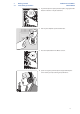
2 2.1 StudioLive™ AI-series Mixers Owner’s Manual Getting Started Level Setting Procedure 3. If you’re using passive speakers, connect them to your power amplifier using speaker cable. 4. Bring down all the faders on your StudioLive to the ∞ setting. 5. Make sure that the Mic/Line knob on Channel 1 is all the way counter-clockwise. 6. Plug your StudioLive into a power outlet and turn it on.
2 2.1 StudioLive™ AI-series Mixers Owner’s Manual Getting Started Level Setting Procedure 7. If your microphone requires phantom power, engage the 48V button on Channel 1 of your StudioLive. 8. Turn on your amplifier or powered monitors. 9. Press the Input button in the Meters section. 10. Speak or sing into your microphone at approximately the same volume you expect during the performance.
2 2.1 Getting Started Level Setting Procedure StudioLive™ AI-series Mixers Owner’s Manual 11. Turn the trim knob on Channel 1 clockwise while watching the first meter in the Fat Channel. Adjust the Channel 1 trim knob until a little more than half of the green LEDs are lit. The red LED at the top of the meter should never light up. 12. Press the Select button on Channel 1. 13. Raise the Channel 1 fader until it reaches “U” (unity gain). 14.
2 2.1 Getting Started Level Setting Procedure StudioLive™ AI-series Mixers Owner’s Manual 15. Bring up the Main fader until you can comfortably listen to your microphone through your speakers. 16. With Channel 1 selected, you can use the Fat Channel to add dynamics processing and EQ.
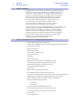
3 3.1 Hookup Rear-Panel Connections 3 Hookup 3.1 Rear-Panel Connections StudioLive™ AI-series Mixers Owner’s Manual Microphone Inputs. Your StudioLive is equipped with 32/24/16 PreSonus XMAX microphone preamplifiers for use with all types of microphones. The XMAX preamplifier has a Class A input buffer, followed by a dual-servo gain stage. This arrangement results in ultra-low noise and wide gain control, allowing you to boost signals without increasing unwanted background noise.
3 3.1 StudioLive™ AI-series Mixers Owner’s Manual Hookup Rear-Panel Connections Line-level Inputs. Each channel of the StudioLive has a ¼-inch, balanced TRS connection for line-level input. When these inputs are engaged, the microphonepreamp circuit is bypassed. Typical examples of line-level connections are synthesizer outputs, CD/DVD-player outputs, and (with exceptions) signal-processor inputs and outputs.
3 3.1 Hookup Rear-Panel Connections StudioLive™ AI-series Mixers Owner’s Manual Aux Outputs. The StudioLive is equipped with 14/10/6 auxiliary outputs. Aux mixes are routed to these outputs. In Section 4.4.5 and 4.4.6, we discuss in detail how to create aux mixes for monitoring and effects processing. Talkback Mic Input. The StudioLive does not have an onboard talkback mic; an external mic must be used.
3 3.1 StudioLive™ AI-series Mixers Owner’s Manual Hookup Rear-Panel Connections Tape In/Out. The StudioLive is equipped with stereo RCA inputs and outputs that can be used to connect a tape deck, CD player, or other consumer device. The tape-input level is controlled by the 2 Track In knob on the top panel. The Main bus is routed post-fader to the tape output. CR Outputs. These are the balanced control-room outputs. The level is controlled by the Monitor knob in the Monitor section on the top panel.
3 3.2 Hookup Front Panel Connections StudioLive™ AI-series Mixers Owner’s Manual 3.1.1 Installed Option Card Each StudioLive AI-series mixer includes an installed option card that provides FireWire s800 connectivity, Ethernet for remote control, and S/PDIF output. For more information about user-installable StudioLive AI-series mixer option cards and their availability, please visit www.presonus.com. FireWire s800 Ports. There are two standard 9-pin FireWire s800 ports on the back of the StudioLive.
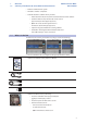
StudioLive™ AI-series Mixers Owner’s Manual 3 3.3 Hookup Typical Band Setup Diagrams 3.3 Typical Band Setup Diagrams backup vocal mics keyboard/DI lead vocal acoustic guitar/DI sax WARNING: Power down unit before removing option card laptop running Capture 2.
3 3.
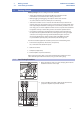
3 3.4 Hookup Typical Church Setup Diagrams 3.4 Typical Church Setup Diagrams hanging choir mics podium mic backup vocal mics StudioLive™ AI-series Mixers Owner’s Manual lead vocal keyboard/DI acoustic guitar/DI piano WARNING: Power down unit before removing option card subwoofers dvd player cry room laptop running Capture 2.
3 3.
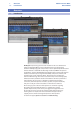
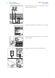
4 4.1 Controls The Fat Channel 4 Controls 4.1 The Fat Channel StudioLive™ AI-series Mixers Owner’s Manual The revolutionary Fat Channel is the heart of the StudioLive. The Fat Channel makes dynamics, routing, and panning for every input and output on the StudioLive available at the touch of a Select button. The 32/24/16 multipurpose knobs and meters located in the Fat Channel control nearly every adjustment you will need to make on your StudioLive.
4 4.1 StudioLive™ AI-series Mixers Owner’s Manual Controls The Fat Channel Channel Info Page. When a channel or output bus is selected, the Channel Info page will open in the LCD. This is the default screen for your StudioLive. From this page you can customize the name for each channel or bus and view helpful information about each channel and bus on your StudioLive mixer. See Section 5.1 for more information. 4.1.
4 4.1 Controls The Fat Channel High Pass Filter. Sets the High-Pass Filter Frequency Threshold for the Selected Channel or Output Bus. The High Pass Filter section consists of an encoder and a meter. Frequency range is indicated to the left of the meter. The filter’s threshold can be set from 24 Hz to 1 kHz. When the meter is set to its lowest point, the filter is off. The high-pass filter’s slope is -12 dB/8va. Power User Tip: A high-pass filter attenuates all frequencies below the set threshold.
4 4.1 Controls The Fat Channel StudioLive™ AI-series Mixers Owner’s Manual Gate Threshold. Sets and Displays the Threshold of the Gate for the Selected Channel. Gate Release. Sets and Displays the Rate at Which the Gate Closes on the Selected Channel. This encoder sets, and the meter displays, the gate threshold for the selected channel. The gate threshold sets the level at which the gate opens.
4 4.1 Controls The Fat Channel StudioLive™ AI-series Mixers Owner’s Manual Compressor Threshold. Sets and Displays the Threshold of the Compressor for the Selected Channel or Output Bus. Compressor Release. Sets and Displays the Compressor Release Setting for the Selected Input Channel or Output Bus. This encoder sets, and the meter displays, the compressor threshold for the selected channel or output bus. When the signal’s amplitude (level) exceeds the threshold setting, the compressor engages.
4 4.1 Controls The Fat Channel StudioLive™ AI-series Mixers Owner’s Manual Low EQ On/Off Button. Turns the Low Band EQ On/Off for the Selected Input or Output Bus. Low EQ Gain Control. Sets and Displays the Gain Attenuation or Boost of the Center Frequency. This button activates the equalizer’s Low band for the selected channel or bus. The button will illuminate to indicate control is active. This encoder sets, and the meter displays, the gain cut or boost at the center frequency for the Low band.
4 4.1 Controls The Fat Channel Low-Mid EQ Frequency Control. Sets and Displays the Center Frequency of the Low-Mid EQ. This encoder sets, and the meter displays, the center frequency for the Low-Mid band. You can adjust the center frequency from 90 Hz to 1.2 kHz. Low-Mid EQ Q Control (32.4.2AI and 24.4.2AI only). Sets and Displays the Q of the Low Mid Frequency Band. This encoder sets, and the meter displays, the Q for the Low-Mid band. The Q is the ratio of the center frequency to the bandwidth.
4 4.1 Controls The Fat Channel High-Mid EQ Q Control (32.4.2AI and 24.4.2AI only). Sets and Displays the Q of the High Mid Frequency Band. This encoder sets, and the meter displays, the Q for the High-Mid band. The Q is the ratio of the center frequency to the bandwidth. When the center frequency is constant, the bandwidth is inversely proportional to the Q, so as you raise the Q, you narrow the bandwidth. 16.4.2AI users can access the variable High-Mid EQ Q Control from VSL-AI and SL Remote-AI.
4 4.1 Controls The Fat Channel High EQ Gain Control. Sets and Displays the Gain Attenuation or Boost at the Center Frequency of the High Frequency Band. This encoder sets, and the meter displays, the gain cut or boost at the center frequency of the High EQ band. The level of the center frequency can be set between -15 and +15 dB. StudioLive™ AI-series Mixers Owner’s Manual Limiter Threshold (32.4.2AI and 24.4.2AI only). Sets and Displays the Threshold of the Limiter for the Selected Channel or Output Bus.
4 4.1 StudioLive™ AI-series Mixers Owner’s Manual Controls The Fat Channel 4.1.4 Sidechaining (32.4.2AI and 24.4.2AI only) As previously mentioned, the key filter can be sidechained to another channel. This allows you to select a different channel as the trigger source for your StudioLive Gate’s Key Filter. Sidechaining has many uses.
4 4.1 Controls The Fat Channel StudioLive™ AI-series Mixers Owner’s Manual 4.1.5 A/B Fat Channel Settings StudioLive AI-series mixers let you create two complete Fat Channel settings for each channel and bus and compare the two using the Alt EQ & Dyn button.
4 4.1 StudioLive™ AI-series Mixers Owner’s Manual Controls The Fat Channel 4.1.6 Fat Channel Panning, Stereo Link, and Link Master Panning for each input and output bus is set on the Fat Channel. The LED display shows the Pan setting, and the encoder to the right of the display controls panning for the selected input or output bus. When two channels are linked as a stereo pair, the LED display will automatically change to a stereo pan. Stereo linking is done within the Fat Channel.
4 4.1 StudioLive™ AI-series Mixers Owner’s Manual Controls The Fat Channel 4.1.8 Copying Fat Channel Settings In addition to being able to create and save custom Fat Channel presets, every setting in the Fat Channel can be copied from one channel or bus to any other channel or bus. 1. Press the Copy button to copy the settings on the selected channel or bus. Every Select button on the StudioLive except the button for the currently selected channel will begin to flash.
4 4.1 StudioLive™ AI-series Mixers Owner’s Manual Controls The Fat Channel 4.1.9 Loading Fat Channel Presets The StudioLive comes with a suite of channel-strip presets created by professional users of PreSonus products. These presets provide a great jumping-off point to create a mix quickly and easily. The StudioLive also allows you to create your own library of presets. 1. To load a preset to any channel on the StudioLive, first press the Select button for the desired channel. 2.
4 4.1 StudioLive™ AI-series Mixers Owner’s Manual Controls The Fat Channel 4.1.10 Saving Fat Channel Presets If you have created a channel-strip setting in the Fat Channel that you would like to save to the Channel Preset library, press the Fat Channel’s Save button. 1. You will notice that the LCD will display the Channel Preset Save menu. Use the Value encoder to scroll to an empty position in the Channel Preset library. 2. Press the Next button to navigate to the category location. 3.
4 4.1 Controls The Fat Channel StudioLive™ AI-series Mixers Owner’s Manual 5. Turn the Value encoder clockwise or counter-clockwise to change the letter. The StudioLive allows you to customize the name with uppercase and lowercase letters, as well as a selection of numerals and punctuation marks. You can insert a space by simply pressing the Tap button. 6. Once you are satisfied with your changes, press the Store button.
4 4.1 StudioLive™ AI-series Mixers Owner’s Manual Controls The Fat Channel 4.1.11 Channel Presets Library Your StudioLive comes with 50 Fat Channel presets custom designed by professional PreSonus users. These presets can be altered, renamed, and overwritten; however, there are 49 additional empty storage locations for you to build your own custom library of channel-strip settings.
4 4.2 Controls Metering 4.2 Metering StudioLive™ AI-series Mixers Owner’s Manual The StudioLive offers flexible metering at the touch of a button.
4 4.2 StudioLive™ AI-series Mixers Owner’s Manual Controls Metering 4.2.2 Subgroup and Main Meters Subgroup Meters. Display the Level of the Subgroups. In the upper-right corner of the StudioLive are the subgroup meters, which display the levels of the subgroup outputs. These meters are scaled from -60 to +18 dBu. Main Bus Meters. Display the Level of the Main Output. In the upper right corner of the StudioLive are the Main meters, which display the output levels of the main stereo bus.
4 4.3 Controls Input Channel Strip StudioLive™ AI-series Mixers Owner’s Manual subgroup fader meter could be registering -58 dBu, and your Main meters will display -52 dBu of signal, but your channel meters still won’t display anything. By now you’re probably wondering just how loud -78 dBu is. Imagine walking into the vocal booth at your favorite professional recording studio and closing the door. The ambient noise of a very quiet room, like a professional vocal booth, is around -80 dBu.
4 4.4 Controls Aux and FX Buses StudioLive™ AI-series Mixers Owner’s Manual Mute Button. Turns Muting On/Off. This button mutes its channel. It will illuminate red when the channel is muted. Where a channel will be muted is determined by the Global Mute setting in the System menu. By default, Global Mute is set to “Yes”. While in this mode, engaging a channel mute button will mute the channel in all of its assigned outputs (subgroups, mains, aux and FX buses).
4 4.4 Controls Aux and FX Buses StudioLive™ AI-series Mixers Owner’s Manual Output Level Control. Adjusts the Master Level of the Aux Output. This knob controls the overall output level of the aux mix. Aux Bus Select Button. Enables Fat Channel Viewing. As previously described in Section 4.1.1, the Select button routes its aux bus through the Fat Channel, allowing you to add dynamics processing and EQ. This will also open the Channel Info page for the selected aux bus in the LCD. 4.4.
4 4.4 StudioLive™ AI-series Mixers Owner’s Manual Controls Aux and FX Buses Mix|Pan Button. Enables Pan Control and Metering in the Fat Channel (Stereo Send Mode Only). When two auxes are stereo-linked, and the Mix button is enabled on the evennumbered aux bus (2, 4, 6, etc.), the Fat Channel encoders become the pan controls for their respective input channels. The meters will display the pan setting of each of the input channels. When the Mix button is enabled on the odd-numbered aux bus (1, 3, 5, etc.
4 4.4 Controls Aux and FX Buses StudioLive™ AI-series Mixers Owner’s Manual 2. By pressing the Select button for Aux 1, you can add dynamics processing and EQ to the overall monitor mix. These are especially useful for eliminating feedback in a monitor. Keep in mind that an equalizer can also be used to increase the presence of an instrument by boosting that particular frequency range without necessarily boosting the volume in the mix.
4 4.4 Controls Aux and FX Buses StudioLive™ AI-series Mixers Owner’s Manual 1. To begin, press the FXA Select button and decide to which outputs you’d like to route your effects mix. 2. To patch your effects mix to any of the subgroups or to the Main outputs, press the desired output’s button in the Assign section of the Fat Channel. 3. Next, press the Mix button in the FXA section. The Fat Channel meters will display the send level of each of the input channels to FXA.
4 4.4 StudioLive™ AI-series Mixers Owner’s Manual Controls Aux and FX Buses 6. To send FXA’s mix to a monitor mix, press that aux bus’s Mix button twice and use Encoder 5 to dial in the right level. (Encoders 6-8 control FXB-FXD’s send levels.) For information on changing the effects preset, type, or parameters, see Section 5.2. 4.4.7 Using an External Effects Processor This section will detail how to use an external effects processor with your StudioLive.
4 4.4 Controls Aux and FX Buses StudioLive™ AI-series Mixers Owner’s Manual 4. In the Fat Channel, assign Aux In A to the main outputs. 5. Press the Mix button for Aux 1. The Fat Channel meters will display each input channel’s send level to Aux 1. The encoders below each meter control the channel’s level in Aux 1’s mix. You will use these encoders to set the send levels for each channel to the effects processor, the same way you used them to create a monitor mix.
4 4.5 Controls Subgroups 4.5 Subgroups StudioLive™ AI-series Mixers Owner’s Manual A subgroup allows you to combine multiple channels into a single bus so that the overall level for the entire group is controlled by a single fader. The StudioLive also allows you to apply the Fat Channel’s noise gate, limiter, compression, and EQ to the group as a whole, in addition to the processing available for each channel. Subgroups can be soloed and muted.
4 4.5 StudioLive™ AI-series Mixers Owner’s Manual Controls Subgroups 4.5.2 Creating Instrument Subgroups Grouping individual instruments that create a section in your mix has obvious advantages: The entire group can be muted or soloed, brought up or down in a mix, and faded in or out for a more polished intro or outro. Some of the most common submix groups are drums, backing vocals, horn sections, and string sections. Drums are a classic application for subgroup mixing.
4 4.5 StudioLive™ AI-series Mixers Owner’s Manual Controls Subgroups 4. In the Fat Channel’s Stereo section (to the right of the Pan display), enable Link. 5. Turn the Pan knob all the way clockwise to set the stereo pan to hard left and right. Now Subgroups 1 and 2 are linked, with Sub 1 panned hard left and Sub 2 panned hard right. The channel panning is preserved. 6. Now assign Subgroup 1/2 to the Main outputs.
4 4.5 StudioLive™ AI-series Mixers Owner’s Manual Controls Subgroups 1. Press the FX button in the Master Control section to access the Effects menu. 2. In the FX C preset load field, use the Value encoder to scroll through the effects library until you find a suitable delay. 3. Press Recall to load it. 4. Press the FXC Select button to jump to the Parameter Detail page. This will display every parameter available for the preset that was loaded, and you can adjust its parameters to taste.
4 4.6 StudioLive™ AI-series Mixers Owner’s Manual Controls Main Output Bus 7. Press the Select button for FX C and assign this bus to Subgroup 3 and unassign it from the Main bus. If you like you can also add some dynamics processing and EQ at this point. 8. Press the Select button for Subgroup 3 and assign the group to the Main output.
4 4.7 Controls Mute Groups (StudioLive 32.4.2AI only) 4.7 Mute Groups (StudioLive 32.4.2AI only) StudioLive™ AI-series Mixers Owner’s Manual The StudioLive 32.4.2AI features six mute groups. A mute group allows you to mute and unmute multiple channels and buses with the press of a single button. With the six mute groups on the StudioLive 32.4.
4 4.8 StudioLive™ AI-series Mixers Owner’s Manual Controls Master Section 4.7.1 Creating a Mute Group (StudioLive 32.4.2AI only) Creating a mute group is quick and easy. In this example, we will be creating a mute group for Channels 1-10, using Mute Group 1. 1. Mute Channels 1-10. 2. Press and hold the Mute Group 1 button. It will flash for one second indicating that it is storing the group. When the group has been stored, it will illuminate. Save Undo 4.
4 4.8 StudioLive™ AI-series Mixers Owner’s Manual Controls Master Section 4.8.2 Talkback System The StudioLive features a Talkback microphone input on the back panel. This can be routed to the aux outputs and to the mains. It is important to note that the aux outputs are grouped in the Talkback section.
4 4.9 Controls Solo Bus 4.9 Solo Bus StudioLive™ AI-series Mixers Owner’s Manual The StudioLive features an independent Solo bus. This feature is extremely useful in setting levels for monitor mixes, dialing in dynamics processing on each channel, and fixing issues during a live show without interrupting the main mix. The Solo bus has three different modes: AFL (default), PFL, and SIP. •• AFL (After-Fader Listen).
4 4.9 StudioLive™ AI-series Mixers Owner’s Manual Controls Solo Bus 4.9.2 Solo Modes From the first page of the System menu, you can choose between three Solo modes. To access these modes, press the System button and navigate to Page 1: Global. Press the Next button to navigate to the Solo Mode field and use the Value encoder to scroll through the three modes: •• Latch: This is the default Solo mode. When Latch Solo mode is active, you can solo multiple channels and buses at once.
4 4.9 StudioLive™ AI-series Mixers Owner’s Manual Controls Solo Bus 2. By default, your StudioLive mixer is set to Latch Solo mode. For the purposes of this tutorial, this is the setting you will need to use. See Section 4.9.2 for more information about solo modes. 3. Next, press the Solo buttons on the channels, auxes, and subgroups you want to monitor. 4. Turn the Solo Level knob in the Solo section to about 12 o’clock. Save Undo 5.
4 4.9 StudioLive™ AI-series Mixers Owner’s Manual Controls Solo Bus 2. Press and hold the SIP button in the Solo section until it illuminates. 3. Raise all your channel faders and your main fader to unity gain. 4. Most engineers start with the drums and work from the bottom up, so press the Solo button on your kick-drum mic channel. Notice that all the other channels on your StudioLive have been muted, and the kick-drum channel is selected. Kick SnareTop SnareBOT HighHat Tom 1 Tom 2 Floor Tom 5.
4 4.10 StudioLive™ AI-series Mixers Owner’s Manual Controls Monitor Bus 7. Once you are satisfied, press the Solo button on the snare-mic channel and repeat steps 4 through 5. In this way, continue with each drum mic and then move on to the other instruments that are connected to the StudioLive. When you have finished with all instruments, press the SIP button again and set up your fader mix. Kick SnareTop SnareBOT 4.
4 4.10 Controls Monitor Bus StudioLive™ AI-series Mixers Owner’s Manual The Headphone output is located on the front of the mixer, below the main fader. Control-Room Monitor Level Control. Adjusts the Overall Level of the ControlRoom Monitor Outputs on the Rear Panel. This knob adjusts the overall level of the control-room monitor outputs.
StudioLive™ AI-series Mixers Owner’s Manual 5 5.1 Digital Effects | Master Control Channel Info Page 5 Digital Effects | Master Control From the Digital Effects | Master Control section, you can select and change the parameters of the four internal effects processors, and you can store and recall every setting on the StudioLive.
5 5.2 Digital Effects | Master Control The Digital FX (Effects) Menu 5.2 The Digital FX (Effects) Menu StudioLive™ AI-series Mixers Owner’s Manual The StudioLive AI mixers feature four internal effects processors. The processors for FX A and FX B are dedicated to reverb and access the StudioLive’s reverb library. The processors for FX C and FX D are dedicated to delay effects and access the StudioLive’s library of delay presets.
5 5.2 StudioLive™ AI-series Mixers Owner’s Manual Digital Effects | Master Control The Digital FX (Effects) Menu 5.2.1 Creating FX Presets Page 1 of the FX menu provides access to your library of effects presets. Pages 2-5 provide access to the 13 FX types. An FX preset is made by adjusting the default parameters of an FX type, so one FX type can be the foundation for many different presets. The StudioLive contains a library of 50 custom reverb and delay presets designed by PreSonus.
5 5.2 StudioLive™ AI-series Mixers Owner’s Manual Digital Effects | Master Control The Digital FX (Effects) Menu 6. To jump to this page, simply press the Store button while you have a field in the desired effect selected, either in the QuickView page, or in the Parameter Detail page. 7. Use the Value encoder to change the library location to which you will store your new effects preset, unless you wish to overwrite the currently selected preset. 8.
5 5.2 Digital Effects | Master Control The Digital FX (Effects) Menu StudioLive™ AI-series Mixers Owner’s Manual 11. If you’d like to store the effects currently loaded on multiple FX buses, simply navigate to the FX Bus field and use the Value encoder to select another bus. 5.2.2 Reverb and its Parameters Reverberation—or reverb, as it is more commonly known—is perhaps the most widely used effect. Natural reverb is created by sound waves reflecting off of a surface or many surfaces.
5 5.2 Digital Effects | Master Control The Digital FX (Effects) Menu StudioLive™ AI-series Mixers Owner’s Manual 5.2.3 Delay and its Parameters A delay essentially creates an echo, although you can often use delays to create more complex time-based effects. The source signal is delayed so that it is heard later than it actually occurred. Note: Delay types and presets can only be loaded on FXC and FXD. The following parameters are available for the four delay types the StudioLive offers: Time.
5 5.2 StudioLive™ AI-series Mixers Owner’s Manual Digital Effects | Master Control The Digital FX (Effects) Menu 5.2.4 Reverb Effects Preset Library REVERB EFFECTS POS. TYPE R1 AMBIENCE POS.
5 5.2 StudioLive™ AI-series Mixers Owner’s Manual Digital Effects | Master Control The Digital FX (Effects) Menu 5.2.6 Digital Effects Types The StudioLive contains 13 different effects types with which you can create custom presets or redesign the included library of presets. NAME POS PARAM (L1) PARAM (L2) PARAM (L2) PARAM (L2) Ambience T1 Reverb Decay (s) Default: 0.69 Range: 0.29 – 1.
5 5.3 Digital Effects | Master Control Scenes 5.3 Scenes StudioLive™ AI-series Mixers Owner’s Manual The StudioLive allows you to create and store a library of scenes. A scene is like a snapshot of your mix. It stores each Fat Channel parameter for every input and bus, as well as each fader’s position, the aux and effects mixes, channel mutes and solos, and the input selection (analog input or digital playback stream). 5.3.
5 5.3 Digital Effects | Master Control Scenes StudioLive™ AI-series Mixers Owner’s Manual 5.3.2 Nulling Parameters To return any Fat Channel parameter to its Zero Out scene setting, simply press and hold the Tap Tempo button and turn its encoder. For example, if you want to null the current setting for the Compressor Threshold on Channel 1: 1. Select Channel 1. 2. Press and hold the Tap Tempo button. 3. Simultaneously turn the Compressor Threshold in the Fat Channel.
5 5.3 StudioLive™ AI-series Mixers Owner’s Manual Digital Effects | Master Control Scenes 2. The memory locations will be selected. Use the Value encoder to scroll to a free location in the Scene library. 3. Now name your scene: Press the Next button to navigate to the first letter of the preset name and turn the Value encoder clockwise or counter-clockwise to change the letter.
5 5.3 StudioLive™ AI-series Mixers Owner’s Manual Digital Effects | Master Control Scenes 3. If you do not wish to recall a certain set of parameters, simply use the Next and Prev buttons to navigate through the screen. When the parameter that you wish to disable is selected, turn the Value encoder counter-clockwise to move it to the No (off) position. Once you have disabled the parameters you do not wish to recall, press the Recall button.
5 5.3 Digital Effects | Master Control Scenes StudioLive™ AI-series Mixers Owner’s Manual It is important to note that the recall groups have no effect on what parameters are stored with a scene. All storable parameters are saved with a scene regardless of what recall groups are enabled. Note: The following StudioLive global parameters are not recallable: •• Input Trim controls •• Output Trim controls •• Subgroup Delay settings •• LCD Contrast •• LCD Brightness •• Link ID •• Sample Rate 5.3.
5 5.3 Digital Effects | Master Control Scenes StudioLive™ AI-series Mixers Owner’s Manual Creating a Quick Scene To create a Quick Scene, dial in a mix you’d like to have access to later, or recall a scene that you want to have instantly available during a show. 1. Press the Scene Store button. All the Quick Scene buttons will start to flash. Store Store Undo 2. Press any of the six flashing buttons to store the scene to the button.
5 5.4 Digital Effects | Master Control Graphic Equalizers StudioLive™ AI-series Mixers Owner’s Manual 5.3.7 AutoStore It is not necessary to create a scene for your StudioLive in order to preserve its settings when you power it down. The StudioLive takes continuous snapshots of the current position of every parameter on the mixer and stores them to memory every 3 seconds.
5 5.4 StudioLive™ AI-series Mixers Owner’s Manual Digital Effects | Master Control Graphic Equalizers 5.4.1 The GEQ Menu Each GEQ on your StudioLive is assigned to a specific bus: Main Left, Main Right, and Auxes 1 through 14/10/6. The bus assignment cannot be changed. When the GEQ menu is active, the meters and encoders of the Fat Channel become the controls for the graphic EQ. As you touch a knob, you will notice that its band number, frequency, and gain are displayed in the System menu.
5 5.4 StudioLive™ AI-series Mixers Owner’s Manual Digital Effects | Master Control Graphic Equalizers 5.4.2 Saving and Loading Graphic EQ Presets Like all other parameters on the StudioLive, graphic EQ settings can be stored and recalled. If you have created a graphic EQ setting that you would like to save to the GEQ Preset library, press the Save button in the Fat Channel while that graphic EQ is active. Notice that the LCD will display the GEQ Save menu. To continue: 1.
5 5.4 Digital Effects | Master Control Graphic Equalizers StudioLive™ AI-series Mixers Owner’s Manual To load a preset to any channel on the StudioLive, first press the GEQ button and page down to the desired GEQ. From the Fat Channel, press the Load button. You will notice that the LCD now displays the GEQ Load menu. Use the Value encoder to locate the preset you would like to use. Once you have made your selection, press the Recall button.
5 5.5 Digital Effects | Master Control System Menu 5.5 System Menu StudioLive™ AI-series Mixers Owner’s Manual In most digital-console manuals, the phrase “System menu” inspires a sense of dread. However, with the StudioLive, you have nothing to fear. The System menu on the StudioLive serves just a few simple functions, most of which have little to do with mixing a show. Like the Scene and FX Menus, the StudioLive remembers on which page of the System menu you were when you navigated away.
5 5.5 StudioLive™ AI-series Mixers Owner’s Manual Digital Effects | Master Control System Menu iOS Devices Your StudioLive AI mixer can be wirelessly remote-controlled with an iPad or iPhone/iPod touch. While this allows you to move about the venue freely, it can also put the full power of the StudioLive in multiple hands — some more adept than others. Therefore, your StudioLive enables you to limit each iOS device’s access to the mixer features by setting permissions.
5 5.5 Digital Effects | Master Control System Menu StudioLive™ AI-series Mixers Owner’s Manual When the StudioLive is connected and synced to a computer, the status will read “Driver On.” This parameter can be adjusted from the StudioLive while it is synced to a computer. (See “Connecting to a Computer” in the StudioLive AI-Series Software Library Manual for details on using your StudioLive as an audio interface.
StudioLive™ AI-series Mixers Owner’s Manual 5 Digital Effects | Master Control 5.5.1 Firmware Updates Lockout Mode The StudioLive features a Lockout mode that allows you to create a password and lock the controls. This is especially useful in situations where several people will be running sound but only one or two are knowledgeable enough to set up dynamics processing and the like. Right out of the box, the StudioLive cannot be locked, so don’t worry about hitting the wrong button.
5 Digital Effects | Master Control 5.5.1 Firmware Updates StudioLive™ AI-series Mixers Owner’s Manual 2. Click on your mixer registration in the My Hardware section and download the firmware files for your mixer. 3. Open your downloads folder and locate the StudioLive firmware folder. The folder will be named with your mixer’s model number and the new firmware version (e.g., SL3242AI_v4733). 4. Depending on your system preferences, the firmware folder may not automatically uncompressed from the .
5 Digital Effects | Master Control 5.5.1 Firmware Updates StudioLive™ AI-series Mixers Owner’s Manual 6. Connect a FAT32-formatted USB thumb drive to your computer. Power User Tip: Most small USB drives (16 GB or less) are already formatted correctly, so no formatting is required. If your computer does not detect your thumb drive, verify that it is formatted correctly. 7. Select all five firmware files and either copy/paste or drag them to the root of your thumb drive.
StudioLive™ AI-series Mixers Owner’s Manual 5 Digital Effects | Master Control 5.5.1 Firmware Updates 11. It will take approximately five seconds for your mixer to detect your thumb drive. Count to five slowly before proceeding to the next step. 1 Louisiana 2 Louisiana 3 Louisiana 4 Louisiana 5 Louisiana 12. Press the System button. 13. Press the Pg Dn button until you reach the last page of the System Menu (Page 9). 14. Press the Recall button. 15.
5 Digital Effects | Master Control 5.5.1 Firmware Updates StudioLive™ AI-series Mixers Owner’s Manual 17. Power down your mixer. Off USB Drive 18. Remove the thumb drive. 19. Insert your USB LAN adapter (if you want to connect wirelessly to your router) and power your mixer back on. Note: Be sure that your speakers are powered off, as there will be a small pop when the mixer reboots.
6 6.1 Resources Stereo Microphone Placement 6 Resources 6.1 Stereo Microphone Placement StudioLive™ AI-series Mixers Owner’s Manual The following are a few recording applications to help you get started with your StudioLive. These are by no means the only ways to record these instruments. Microphone selection and placement is an art. For more information, visit your library or local bookstore, as there are many books and magazines about recording techniques.
6 6.1 Resources Stereo Microphone Placement StudioLive™ AI-series Mixers Owner’s Manual Acoustic Guitar Point a small-diaphragm condenser microphone at the 12th fret, approximately 8 inches away. Point a largediaphragm condenser microphone at the bridge of the guitar, approximately 12 inches from the guitar. Experiment with distances and microphone placement. Another popular method is using an XY microphone placement with two small-diaphragm condenser microphones.
6 6.1 Resources Stereo Microphone Placement StudioLive™ AI-series Mixers Owner’s Manual Drum Overheads (XY example) Place two small-diaphragm condenser microphones on an XY stereo-microphone holder (bar). Position the microphones so that each one is at a 45-degree angle, pointed down at the drum kit, approximately 7 or 8 feet above the floor or drum riser. Experiment with height. This technique can be used in live applications as well.
6 6.2 Resources Compression Setting Suggestions 6.2 Compression Setting Suggestions StudioLive™ AI-series Mixers Owner’s Manual The following are the compression presets that were used in the PreSonus BlueMax. We have included them as a jumpingoff point for setting up compression on the StudioLive. Vocals Soft. This is an easy compression with a low ratio setting for ballads, allowing a wider dynamic range. It’s good for live use. This setting helps the vocal “sit in the track.
6 6.2 StudioLive™ AI-series Mixers Owner’s Manual Resources Compression Setting Suggestions Keyboards Piano. This is a special setting for an even level across the keyboard. It is designed to help even up the top and bottom of an acoustic piano. In other words, it helps the left hand to be heard along with the right hand. THRESHOLD RATIO ATTACK RELEASE -10.8 dB 1.9:1 108 ms 112 ms Synth.
6 6.3 Resources EQ Frequency Guides 6.
6 6.
6 6.4 StudioLive™ AI-series Mixers Owner’s Manual Resources EQ Setting Suggestions Pop Male Vocals LOW ON/OFF LOW SHELF LOW FREQ (Hz) LOW Q LOW GAIN LOW MID ON/OFF LOW MID FREQ (Hz) LOW MID Q LOW MID GAIN ON OFF 225 0.3 -2 ON 960 0.3 0 HIGH MID ON/ OFF HI MID FREQ (kHz) HIGH MID Q HIGH MID GAIN HIGH ON/OFF HIGH SHELF HIGH FREQ (kHz) HIGH Q HIGH GAIN ON 2.0 0.6 +2 ON OFF 7.2 0.
6 6.4 StudioLive™ AI-series Mixers Owner’s Manual Resources EQ Setting Suggestions Fretted Instruments Electric Bass LOW ON/OFF LOW SHELF LOW FREQ (Hz) LOW Q LOW GAIN LOW MID ON/OFF LOW MID FREQ (Hz) LOW MID Q LOW MID GAIN ON ON 36 N/A -8 ON 130 0.4 +4 HIGH MID ON/ OFF HI MID FREQ (kHz) HIGH MID Q HIGH MID GAIN HIGH ON/OFF HIGH SHELF HIGH FREQ (kHz) HIGH Q HIGH GAIN ON 2.0 0.6 +4 ON ON 4.
6 6.5 Resources Technical Specifications 6.5 Technical Specifications StudioLive™ AI-series Mixers Owner’s Manual Microphone Preamp Type XLR Female, balanced Frequency Response to Direct Output (at unity gain) 20 Hz-40 kHz, ± 0.5 dBu Frequency Response to Main Output (at unity gain) 20 Hz-20 kHz, ± 0.5 dBu Input Impedance 1 kΩ THD to Direct Output (1 kHz at unity gain) <0.007%, +4 dBu, 20 Hz–20 kHz, unity gain, unwtd THD to Main Output (1 kHz at unity gain) <0.
6 6.
6 6.5 StudioLive™ AI-series Mixers Owner’s Manual Resources Technical Specifications Graphic EQ 31-Band 1/3rd Octave Controls Curve-fitting algorithm Gain/Attenuation ±15 dB Digital Audio ADC Dynamic Range (A-wtd, 48 kHz) 118 dB DAC Dynamic Range (A-wtd, 48 kHz) 118 dB FireWire s800, 800 Mb/s Internal Processing 32-bit, floating point Sampling Rate 44.
6 6.6 Resources StudioLive AI Mixers Block Diagrams 6.6 StudioLive AI Mixers Block Diagrams StudioLive™ AI-series Mixers Owner’s Manual We’ve finally made block diagrams too large for our printed manuals. Please visit the following pages on our website for the latest Block Diagrams for all three StudioLive AI-series mixers in Adobe PDF format: http://www.presonus.
6 6.7 Resources StudioLive 32.4.2AI Recall Sheet 6.7 StudioLive 32.4.
6 6.7 StudioLive™ AI-series Mixers Owner’s Manual Resources StudioLive 32.4.
6 6.8 Resources StudioLive 24.4.2AI Recall Sheet 6.8 StudioLive 24.4.
6 6.8 StudioLive™ AI-series Mixers Owner’s Manual Resources StudioLive 24.4.
StudioLive™ AI-series Mixers Owner’s Manual 6 6.9 Resources StudioLive 16.4.2AI Recall Sheet 6.9 StudioLive 16.4.
6 6.10 StudioLive™ AI-series Mixers Owner’s Manual Resources StudioLive 16.4.2AI Rack Ear Installation Artist Scene Date AU X I NP U T S AUX LEVEL AUX IN A SOURCE AUX LEVEL Notes AUX IN B SOURCE Notes A B A U X SE ND S AUX LEVEL AUX SEND AUX Notes AUX SEND Notes 1 4 Monitor Send Notes Monitor Send Monitor Send Monitor Send Notes 2 5 Monitor Send Notes Notes 3 6 Monitor 6.10 LEVEL Send StudioLive 16.4.
7 7.1 Troubleshooting and Warranty Troubleshooting 7 Troubleshooting and Warranty 7.1 Troubleshooting StudioLive™ AI-series Mixers Owner’s Manual Please check the PreSonus Web site (www.presonus.com) regularly for software information and updates, firmware updates, and support documentation, including frequently asked questions. Online technical support is available to registered users through their My PreSonus account. Visit my.presonus.com to register.
7 7.2 Troubleshooting and Warranty PreSonus Limited Warranty StudioLive™ AI-series Mixers Owner’s Manual Main Fader Doesn’t Control Mix Level Verify that your monitors are connected to the Main outputs on the rear panel of your StudioLive, not the Control Room outputs. Verify that StudioLive is not in Fader Locate mode. 7.2 PreSonus Limited Warranty PreSonus Audio Electronics, Inc.
Dinner is Served Added bonus: PreSonus’ previously Top Secret recipe for… Chicken and Andouille Gumbo Ingredients: •• •• •• •• •• •• •• •• •• •• •• •• •• •• •• •• 1 C All-Purpose flour ¾ C Vegetable Oil 1 large onion (diced) 1 small onion (quartered) 6 celery stalks (diced) 1 large green bell pepper (diced) 3 cloves garlic (2 minced, 1 whole) 1 lb link Andouille sausage 4 Chicken leg quarters 4 qt water 4 bay leaves 1 tsp thyme 1 tsp Old Bay seasoning 1-2 C frozen okra, sliced ¼ C fresh parsley, minced 6-
StudioLive AI-Series Mixers ™ Digital Mixing System with Active Integration ™ Owner’s Manual ® 18011 Grand Bay Ct. • Baton Rouge, Louisiana 70809 USA• 1-225-216-7887 www.presonus.