
Manual


18
4 Controls
4.1 The Fat Channel
StudioLive™ AI-series Mixers
Owner’s Manual
4 Controls
4.1 The Fat Channel
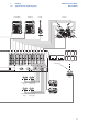
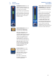
The revolutionary Fat Channel is the heart of the StudioLive. The Fat Channel
makes dynamics, routing, and panning for every input and output on the
StudioLive available at the touch of a Select button. The 32/24/16 multipurpose
knobs and meters located in the Fat Channel control nearly every adjustment
you will need to make on your StudioLive. From the Fat Channel, you can:
• Add dynamics processing and EQ to every input and output and A/B them
• Create sends and effects mixes for every analog aux bus and internal effects buses
• Assign subgroup and main routing
• Meter inputs, post-dynamics-processing outputs, and
gain reduction for every input channel
• Meter aux-send outputs
• Copy, save, and load mix scenes
• Recall your fader position for stored mixes
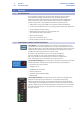
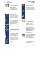
4.1.1 Select Buttons, Meters, and the Fat Channel
Select Buttons. All around the StudioLive, you will see Select buttons. There is a
Select button on each of the input channels, each of the analog aux buses, all of the
internal FX (effects) buses, each of the subgroups, both auxiliary inputs, and the main
output bus. Each of these buttons serves exactly the same purpose: to access the
available Fat Channel parameters for its channel or bus.
It should be noted that while the noise gate, compressor, EQ, and
limiter are available on every input channel and bus, the high-pass
filter is only available on the input channels, aux buses, and internal FX
buses, and Polarity Invert is only available on the input channels.
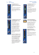
Selected Channel Display. In the lower right corner of the Fat Channel, you will find
an LED readout. The currently selected channel will always be displayed here.
• Input Channels: Channel number
• Subgroup: S1-S4
• Aux Outputs: A1-A9, AA-AE
• FX Buses A-D: FA-FD
• Auxiliary Input A and B: RA and RB
• Main Bus: MA
Selected Channel Meters. In addition, two meters—part of a set of eight meters
located in the top right section of the mixer—are dedicated to displaying
information about the currently selected channel. The meter on the far left of this
section displays the pre-fader input level for the selected channel. The meter to the
right of it displays the gain reduction applied to the selected channel. It is important
to mention that these meters are only active when one of the input channels or an
aux bus is selected.