
Inc Scanner User Manual

Pressure Systems, Inc. 98RK-1 & 9816 User’s Manual©
Page 142 www.PressureSystems.com
computer and the NetScanner
™
System module are both properly configured for TCP/IP
communications.
If an error free ping reply was not received, rerun the ping application using the IP address of
the host computer. This will verify if the TCP/IP protocol was properly configured on the host
computer. If a ping reply was not received, verify the TCP/IP installation steps for your host
computer. Also verify that the host computer is configured for the proper IP address and subnet
mask.
If the ping test of the host computer’s IP passed while the ping of the NetScanner
™
System
module failed, check the following possible sources for error:
● Ensure the NetScanner
™
System module’s IP has been assigned (as explained
in Section 6.1.3.1) and the correct IP was used for the ping test.
● Ensure the IP address of the host computer and the NetScanner
™
System
module are not duplicated on the network.
● Ensure the link (LNK) LEDs are active on both the 9816 and the 98RK-1 for the
installed slot. Also ensure the link LEDs are active on the host computer’s
Ethernet adapter and the optional hub or switch to which it is attached as well as
the 98RK-1 Host Link LED.
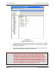
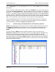
● Ensure the Ethernet adapter card installed in the host is properly configured
without conflict. In Windows
®
, this can be verified by entering the
CONTROL PANEL under SETTINGS. Under CONTROL PANEL select the
SYSTEM icon. When the DEVICE MANAGER tab is selected, a list of all
installed hardware devices will be listed. Any possible hardware conflicts will be
marked in this list with a yellow warning symbol next to the device in question.
● Ensure the Ethernet adapter is configured for 10 Mbit/Sec. Many adapters are
capable of higher speeds that are not compatible with the NetScanner
™
System
modules.
6.2 Zero and Gain Calibration Troubleshooting
Incorrect pneumatic setup or incorrect command usage when executing a module’s Re-zero or
Span calibration command (see 'Z', ‘h’, and 'C' commands in Chapter 3) can result in
unexpected module operation. A common source of errors during these operations is incorrect
control of the module’s internal calibration valve and pneumatic inputs.
Pressure connections are described in Chapter 2 while details of calibration procedures are
described throughout Chapter 4. Some common errors and problems are listed below. These
common problems apply primarily to Model 9816, with its internal transducers and calibration
manifold.
● The module’s supply air is either not attached or does not provide enough
pressure (less than 65 psig) to shift the calibration valve. This results in the
calibration valve remaining in its current position even though the module
commands have requested movement of the valve. This causes incorrect
pneumatic inputs during calibration commands. Verify this by reading the