INSTALLATION INSTRUCTIONS Pyramid Classic Model Hoods (PC) Intended for Domestic Cooking Only READ AND SAVE THESE INSTRUCTIONS Installer: Leave this manual with homeowner Homeowner: Use and Care Information inside Prestige America - 103 Fairfield Rd.
- Table of Contents Important Safety Instructions...................................................1 - 2 Handling Precautions....................................................................2 Packing List for PC 24” Deep Series Hoods.................................3 Important Ventilation Information Before You Begin......................4 Cleaning and Maintenance............................................................5 Planning your Location..........................................................
IMPORTANT SAFETY INSTRUCTIONS PRESTIGE HOODS ARE FOR RESIDENTIAL USE ONLY! CAUTION: FOR GENERAL VENTILATION USE ONLY. DO NOT USE TO EXHAUST HAZARDOUS OR EXPLOSIVE MATERIALS OR VAPORS 1. Use this unit only in the manner intended by the manufacturer. (If you have questions, contact the manufacturer at 800-358-8886. 2. Before servicing or cleaning the unit, switch power off at service panel and lock the panel to prevent power from being switched on accidentally.
d) Use an extinguisher only if: 1) You know you have a class ABC extinguisher and you already know how to operate it. 2) The fire is small and contained in the area where it started. 3) The fire department is being called. 4) You can fight the fire with your back to an exit. HANDLING PRECAUTIONS 1. Remove all rings, watches, belt buckles, jewelry and any clothing with metal buttons or snaps to prevent damage to hood. 2. DO NOT REMOVE HOOD FROM ITS ORIGINAL CARTON UNTIL YOU ARE READY TO INSTALL IT. 3.
INSPECT ALL MOLDED PACKAGING FOR PARTS BEFORE DISCARDING. ANY DAMAGE MUST BE REPORTED BEFORE INST ALLING THE HOOD. ONCE THE HOOD HAS BEEN INSTALLED, NO RETURN WILL BE ACCEPTED.
IMPORTANT VENTILATION INFORMATION BEFORE YOU BEGIN - PC Model hoods can be ducted to the rear with the use of a 90 degree elbow. (NOT SUPPLIED) Check product guide for additional transtions, wall caps, and roof caps. - PC3024 hood CANNOT accept the IBPC1200 internal blower. - PC3624 hood’s duct size is 10” round when using the IBPC1200 internal blower. (STARTER COLLAR SUPPLIED.
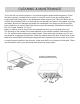
CLEANING & MAINTENANCE Your hood will not function properly if not cleaned regularly and maintained properly. Clean the filters regularly, (at least twice a month or every 24 hours of use) by soaking them in soapy water and rinsing them in the dishwasher at the normal cycle. When the filters are removed, the accessible interior of the hood can be cleaned from grease, using again only soap and water. Burned out Halogen light bulbs are exchanged in the same way as normal light bulbs.
PLANNING YOUR LOCATION Select the proper height to mount the hood. Take into consideration the stature of the person or persons who will be cooking. A height of 30” to 36” above the cooking surface will suit most users. If mounted at a height greater than 36” above the cooking surface, the hood should be at least 6” wider that the cooking appliance to provide proper capture of heat and grease.
PLANNING YOUR LOCATION HEIGHT OF THE HOOD The bottom of the hood should be 30” (76.2 cm) min. to 36” (91.4 cm) max. above the countertop. This would typically result in the bottom of the hood being 66” (167.6 cm) to 72” (175.3 cm) above the floor. The bottom of the hood should never be more than 72” (182.9) above the floor or more than 36” (91.4 cm) above the countertop. These dimensions provide for safe and efficient operation of the hood. WALL INSTALLATION 30” (76.2 cm) Min. 36” (91.4 cm) Max.
INSTALLATION GUIDE & WIRING DIAGRAM Installation of Internal Blower Kit (IBPC600 600CFM) 1.) Remove shipping bracket from hood. DO NOT DISCARD SCREWS. 2.) Install blower bracket with the screws removed from the shipping bracket. 3.) Locate the terminal block inside the electrical supply box. 4.) Connect Fan #1 wire (RED) to terminal block #4. 5.) Connect Fan #1 wire (BLACK) to terminal block #6. 6.) Connect the 115 volt supply wire (WHITE) to terminal block #2. 7.
INSTALLATION GUIDE & WIRING DIAGRAM Installation of In-Line or Remote Blower 1.) Locate the terminal block inside the electrical supply box. 2.) Connect Fan #1 wire (RED) to terminal block #4. 3.) Connect Fan #1 wire (BLACK) to terminal block #6. 4.) Connect the 115 volt supply wire (WHITE) to terminal block #2. 5.) Connect the 115 volt supply wire (BLACK) to terminal block #1. WIRING DIAGRAM (This wiring diagram is also found on the utility cover.
INSTALLING THE WALL HOOD DUCT COVER 1.) Measure from top of the canopy to ceiling and subtract 1/8” (0.3 cm) for clearance. 2.) Place the duct cover top inside the duct cover base and lower until desired height is found. (To eliminate scratches, make a mark on the duct cover top for the desired lowering point by subtracting 15” from the total height needed.) 3.) Use the retaining screws to fasten in place. 4.) Slide the duct cover in place and fasten from inside canopy using the sheet metal screws provided.
WARRANTY INFORMATION Prestige Remote Blowers are warranteed to be free from defects in materials and workmanship, under normal household use for a period of : ONE (1) YEAR Prestige will warranty all parts and related labor to replace them, during the one (1) year warranty period. This applies to the actual parts and normal labor and excludes all other costs, removal and re-installation.