Models covered by these instructions: UIB, UIBTF, CMUIB, UIM Ventilation Inserts & Liners Intended for Domestic Cooking Only READ AND SAVE THESE INSTRUCTIONS Installer: Leave this manual with homeowner. Homeowner: Use and Care information inside. Prestige America Ltd. 103 Fairfield Rd.
-Table of Contents Important Safety Instructions…………………………………………………….1 Handling Precautions……………………………………………………………...2 Important Ventilation Information Before You Begin…………………………2 Parts Sold Separately…………………………………...…………………………3 Cleaning and Maintenance………………………………………………………..3 Packing List for your Inserts a) UIB Inserts with Blowers...………………………………………………………..3-4 b) UIB Inserts without Blowers...………………………………………………………4 c) UIM Inserts………………...
-Important Safety InstructionsPRESTIGE HOODS ARE FOR RESIDENTIAL USE ONLY! CAUTION: FOR GENERAL VENTILATION USE ONLY. DO NOT USE TO EXHAUST HAZARDOUS OR EXPLOSIVE MATERIALS OR VAPORS. 1. Use this unit only in the manner intended by the manufacturer. (If you have questions, contact that manufacturer at 800.358.8886. 2. Before servicing or cleaning this unit, switch power off at service panel and lock the panel to prevent power from being switched on accident.
-Handling Precautions1. Remove all rings, watches, belt buckles, jewelry and any clothing with metal buttons or snaps to prevent damage to hood. 2. DO NOT REMOVE INSERT FROM ITS ORIGINAL CARTON UNTIL YOU ARE READY TO INSTALL IT. 3. When you are ready to begin the installation process, remove the insert from its carton and place it on a clean soft blanket. 4. Inspect the insert carefully for any damage or imperfections before you begin to install the insert.
Parts Sold Separately In-line blowers IL600, IL1200 and IL1600 Remote blowers, RB1000, RB1200, RB1600, RB2000 Transitions TR6x15/8, TR6x15/10 (for use with S2 blower system), TRC8/6 transition collar (for use with S1 blower) Wall Caps, WC6HD, WC8HD, WC10HD. The WC6x15/HD is for use with the S2 blower system when rear ducting. Roof Caps RC6 and RC10 will accommodate 6" to 10" round duct sizes. Backdraft damper BD8 or BD10 (in-line 8" or 10" section duct with backdraft damper installed.
Packing List for your UIB Insert (continued) UIB34S2, UIB40S2 Two (2) Blowers Pre-Installed in Unit Two (2) Stainless Steel Baffle Filters Two (2) Pre-Installed Lights Lid for Electrical Box Use and Care Manual with Wiring Diagram Transition Required and NOT supplied UIB46S2, UIB52S2, UIB58S2 Two (2) Blowers Pre-Installed in Unit Three (3) Stainless Steel Baffle Filters Three (3) Pre-Installed Lights Lid for Electrical Box Use and Care Manual with Wiring Diagram Transition Required and NOT supplied UIB58S2
Packing List for your UIB Hood Liner UIB280WC15 One (1) Stainless Steel Baffle Filters Two (2) Pre-Installed Lights Lid for Electrical Box Use and Care Manual with Wiring Diagram Starter Collar Included UIB340WC15, UIB400WC15 Two (2) Stainless Steel Baffle Filters Two (2) Pre-Installed Lights Lid for Electrical Box Use and Care Manual with Wiring Diagram Starter Collar Included UIB460WC15, UIB520WC15, UIB580WC15 Three (3) Stainless Steel Baffle Filters Three (3) Pre-Installed Lights Lid for Electrical Box U
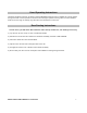
Wiring Diagram Installation Guide for your insert 1.) Choose an installation height comfortable for the user. IMPORTANT: Most building codes require a 30" clearance from the top of a surface burner to the underside of any combustible material. 2.) Choose the appropriate cut-out dimension from the enclosed planning guide. Mark the underside of the wood hood, alcove, or hearth making sure you leave adequate clearance for the stainless steel trim overlay and body of the hood liner. Cut along your marked line.
Hood Operating Instructions The blower should be turned on for about 5 minutes BEFORE cooking in order to establish air currents upward through the hood. Use low speeds for normal use and the higher speeds for strong odors or fumes. Minimize drafts across the range or cooktop, they will reduce the effectiveness of the hood. Rear Ducting Instructions In some cases, you will not be able to duct the unit to the top. In that case, rear ducting is necessary. 1.
Instructions for connection of Wall Switch Kit (UIBWSK) 1.) Disconnect wires from Fan and Light switches from the wiring harness supplied with your hood. 2.) Connect Fan and Light wires from wiring harness to Fan and Light wires on Wall Switch Kit. There will be 2 wires coming from the wall switch kit and 2 wires from the wiring harness for EACH switch. 3.) Before hanging your hood and wall switch kit, be sure that the connections made are fully operational.
se 2) ic
) ST
d UCT.