F I + Z Lens Control Rev 5.
Preston Cinema Systems 1659 Eleventh Street Santa Monica, CA 90404 Table of Contents I. Introduction p-3 A. System B. Hand Unit 3 C. Micro Force Zoom D. Remote Iris Box E. Optional Wireless Units F. MDR3 G. DM-1X, DM-2, DM4 motors H. DXL Module II. FI+Z Basic Operation Summary p-4 A. Motor Driver and Digital Motor set-up B. Hand Unit 3 III. Hand Unit Detailed Description A. Hand Grip 1. Configurations 2. Changing the hand grip B. HU3 Set-Up and Operation 1. Main Display 2. Menu Screen 3.
VI. MDR3 Brackets VII. Battery Packs and Charger p-22 VIII. Technical Information p-23 A. FCC Statement B. Connector Pin-Outs 1. Hand Unit 2. MDR3 C. MDR3 Camera Cable list D. Transmitter Channels and Frequencies p-24 p-24 p-25 I. Introduction A. System. The FI+Z system controls the complete array of lens and camera functions.
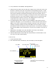
bright fluorescent background for excellent visibility under all lighting conditions. The rings are automatically illuminated in low light conditions by a pair of white LED's. Once a lens is calibrated, it can immediately be used with any of the focus rings. The onboard lens library holds data for 255 lenses. Calibration for a lens change only requires the few seconds needed to choose the lens from the library. A bright, sharp, OLED display shows camera, lens, and hand unit set-up status.
A. Set-up the Motor driver (MDR3) and Digital Motors. a. Slide the motor brackets onto the matte box support rods. Position the motors and brackets so that the motor gears mesh with the corresponding lens gears. Couple the lens motors to the lens gears. Adjust the motor positions relative to the lens to have minimum backlash and tighten the handles of the motor brackets. Do not couple the motor to the lens too tightly or binding will result.
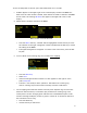
To turn off the power to the unit, press the Power Switch for 3 seconds. c. If MDR3 appears in the upper right corner of the display, the HU3 and MDR3 are both set to the same wireless channel. If the wireless channels of the HU3 and MDR3 do not match, the message No Host! will appear in the upper left corner of the display. d. Match the HU3 wireless channel to the MDR3: Menu Screen: Channel Selection · Press the Menu soft key. “Channel” will be highlighted.
· · · · · · Press Choose. Select the lens location (All lenses, My List A…..) Select the lens and press OK or the Enter key (the center of the Nav key). Set the lens to infinity (as directed) and Enter/Next. Press Ring and choose a focus ring with the desired near focus. Install the same focus ring on the focus knob.
III. Hand Unit 3. Detailed Description A. Grip Configurations. 1. The Hand Unit can be set-up with a molded Hand Grip for Focus and Iris control or with the Hand Grip replaced by a flat cover to accommodate a bracket and Micro Force zoom control. HU3 with Micro Force and bracket 4336 HU3 with Hand Grip and Quick Release Plate 2. Removing the Hand Grip. The Handgrip is removed to allow the bracket for the Micro Force to be installed. · · · · Press the Grip Release toward the HU3 housing (1).
B. Set-Up and Operation 1. Main Display Screen. Press the Power Switch momentarily. The OLED display will show the Main Display Screen : Host MDR Focus Ring Letter Radio Channel Signal Strength bars Battery Charge Lens Selection Shows focus distance in digital format (Lens must be calibrated) All functions are accessed through the Menu key Main Display Screen 2. Menu Screen Options. Press the MENU soft-key; the MENU screen appears. 3.
The Choose key (Fig. 6.1) brings up the list of folders containing lens data (Fig 6.2). The All lenses folder contains data on all of the lenses stored in the HU3 lens library. The Library stores up to 255 lenses. Next brings up the contents of the selected folder (Fig 6.3). The folders My list A, B, and C are used to store up to 15 lenses (3 screens) so that they can be accessed quickly without having to scroll through the complete list.
To calibrate the lens press Edit (Fig 6.12). Select Calibrate Focus with the Nav key (Fig 6.13), and press OK or ENTER). Fig 6.13 Fig 6.14 After the lens focus ring is set to infinity (FIG 6.14), the display indicates the first of ten calibration distances (FIG 6.15). There are two versions of this display screen, one for lenses with linear focus mechanisms, and a second for lenses with non-linear focus. Choosing a lens type automatically brings up the corresponding display screen.
To select the focus ring, →Menu (Fig 6.22) → Ring (FIG 6.21) and use the Navigation key ↕ to select either a ring (A – E) for metric or (Ai – Ei for imperial) (Fig. 6.23. The tables below show the near focus distances for both the rings calibrated in imperial and metric units. Ring Ai Bi Ci Di Ei Near Focus 9” 18” 24” 36” 72” Ring A B C D E Near Focus .25m .50m .70m 1.0m 3.0m The printed labels Ai - Ei are pictured in Fig. 6.24 below.
Fig 7.2 shows the focus axis selected. To re-allocate the focus axis, tap the right side of the Nav key to highlight “Focus”, Fig. 7.3. The north/south sides of the Nav key are then used to cycle the axes: Focus→Iris→Zoom→Off. The “Off” selection is used when one of the HU3 axes is being over-ridden by either a Focus/Iris or Radio Microforce hand unit.
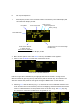
Select Menu →System + Enter to see the System Info screen (Fig. 8.1). Pressing the NETWORK key (Fig. 8.2) initiates a scan of all HU3 channels. The Occupied Channels screen (Fig. 8.3) lists the channels in use and their signal strength. The Region key adjusts the output power of the microwave link to comply with local regulations The Network scan function (Fig. 8.2) will only detect G4 devices; it will not detect Wi-Fi, Bluetooth, frequency hopping devices, etc. Press the Light soft key (Fig.8.
Lens limits can be used to lock a motor to a given position. This is done by setting a zerospan, where the beginning and end of the range are the same point. To lock a motor, position the motor to the desired point and press the set button twice. 11. Panatape and Cine Tape Interfaces. The Panatape and Cinetape units can be used to provide a distance reading that is displayed by the HU3 main display screen.
13. Software updates can be downloaded from the website http://www.prestoncinema.com/downloads.html. To load an update into the HU3: · Install the boot loader program from the CD which is shipped with the FI+Z system to a PC. · · Make sure that the Hand Unit is not powered. Connect the serial cable 4651(serial connector to 4-pin Lemo) between the serial port of the pc and the Serial receptacle on the rear cover of the HU3. · · For laptops without a serial connector, use a USB to serial adapter.
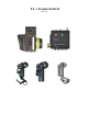
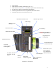
IV. MDR3. Detailed Description MDR3: Torque and Direction Switches MDR3: Channel Display & Switches - Top Input/Output Connectors Channel Display & Switches - Side The four channel MDR3 Motor Driver controls up to four motors, providing control signals to the camera, and transfers camera operating data to the wireless network through the transceiver module. The MDR3 uses a lens calibration sequence to determine the mechanical limits of the zoom, focus, and iris rings of the lens.
button adjacent to the corresponding connector. The bottom row of buttons controls the torque and the upper row controls the direction. · At each press of the torque button, the LED color changes to indicate the maximum torque level: blue minimum, green mid-level, red – maximum. · Pressing the direction button changes the motor direction to correspond with the Hand unit. The white LED indicates the status. · After approximately 4s from the last button press, the display will turn off.
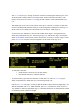
take data from the Cooke i-Lens using cable p/n 4544. The distance data is shown on the HU3 display. · It can send motor position and camera data to an external device. Time Code A. Jamming TC with a Clockit device. After connecting the Clockit to the MDR3 with cable 4731, the HU3 will indicate that its TC is synced (see picture below). This feature requires that the HU3 is running firmware version 2.14 or later. B. MDR3 time code accuracy and stability.
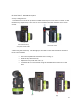
V. Digital Motors DM-1X p/n 4505 DM-1X p/n 4205A (integral bracket) DM2 p/n 4201A (integral bracket) DM4X p/n 4206 & 4206A both have integral brackets The DM-1X is a high speed and high power motor. It is specifically recommended for driving the focus ring of cinema lenses. The DM-2 is a smaller and lighter weight motor. It is recommended for driving the zoom and iris of all lenses, and the focus for all but very stiff lenses. The DM4X motor (right) is the smallest member of the family.
A. Digital Motor Brackets. The integral bracket (“A” version) provides for simplified mounting and also allows the motors to be positioned very close to one another. A rosette gear securely locks the swing arm in position. See pictures on previous page. Important tip for integral brackets: to prevent the motor position from changing as the handles are tightened, first tighten the handle which clamps the motor to the rod and then tighten the rosette handle.
VI. MDR3 Brackets p/n 4790 MDR3 V-lock bracket MDR3 mounted on F55 with V-lock bracket A. Third party suppliers of MDR3, MDR4 brackets and accessories: a. www.cleanscamerasupport.com c. www.woodencamera.com b. www.film-stuff.com/remote-focus-accessories.html VII. Battery Packs and Charger The HU3 uses FM-500 type LI-Ion Battery Packs. The batteries have a rating of 7.4v @ 1.5 ~ 1.8 AH. They provide a typical run time of 6 hours. The typical charging time is 4 hours.
VIII. Technical Information A. FCC Statement This device complies with part 15 of the FCC Rules. Operation is subject to the following two conditions: (1) This device may not cause harmful interference, and (2) this device must accept any interference received, including interference that may cause undesired operation. This equipment has been tested and found to comply with the limits for a class B digital device, pursuant to part 15 of the FCC Rules.
B. Connector pin-outs 1. Hand Unit Connectors 1 Command Serial Zoom Remote Iris Gnd +12V +PWR + Pot 5-pin 4-pin 6-pin 3-pin 2 +12-24VDC GND Gnd Wiper 3 Serial Data Serial In Run -Pot 4 SerialData Serial Out Run (mom) 5 n/c Vref 6 Zoom Cmd. 2. MDR Connectors 1 2 3 4 5 6 7 Command Serial Power Motor Camera Gnd +24 +12V Gnd Gnd +24 Motor(+) Motor(-) Gnd Ext.
4755 4757 Sony F55 Canon C300/500 R/S 4-pin Hirose R/S 2.5mm stereo jack 5. Video Lenses p/n Lens Model Description Connector 4749 Canon HD VTR, zoom 20-pin 4748 Fujinon VTR, zoom 12-pin D.