SOFTWARE VERSION 1.6 WWW.PRG.
AutoPar®, Bad Boy®, PRG Series 400®, Mbox Extreme®, V676®, Virtuoso®, Virtuoso® DX, Virtuoso® DX2, and VL6C+™ are trademarks of Production Resource Group, LLC, registered in the U.S. and other countries. All other brand names which may be mentioned in this manual are trademarks or registered trademarks of their respective companies. This manual is for informational use only and is subject to change without notice. Please check www.prg.com for the latest version.
FOREWORD Compliance Notice This device complies with Part 15 of the FCC rules. Operation is subject to the following two conditions: 1) This device may not cause harmful interference, and 2) This device must accept any interference received, including interference that may cause undesired operation.
WARNING: INSTRUCTIONS FOR PROTECTION AGAINST INJURY TO PERSONS 1) Exterior surfaces of the luminaire will be hot during operation. Use appropriate safety equipment (gloves, eye protection, etc.) when handling and adjusting hot equipment and components. Service and maintenance should be performed only by qualified personnel as determined by the high pressure lighting fixture manufacturer. 2) Arc lamps generate intense heat. Disconnect power and allow lamp to cool for 5 minutes before relamping.
Notes de sécurité Avant de procéder à l’installation des produits décrits dans ce guide et de les mettre en marche, il est extrêmement important de lire TOUS les renseignements et TOUTES les directives de sécurité contenues dans ce guide ainsi que toute documentation jointe. Tenir compte de tous les avertissements et suivre toutes les précautions pendant l’installation et l’utilisation de cet appareil.
Revision History This manual has been revised as follows: IV Version Release Date Notes BASIC February 27, 2009 A May 21, 2009 Software version 1.1. Updated menu system, spin mode values, and troubleshooting chart. Added Bypass Calibration, Gobo Set Zero Position, and Software Update procedures. B July 9, 2009 Added additional hanging instructions, photometrics, and power consumption chart. Updated various menu and operational details. C December 15, 2009 Software version 1.5.
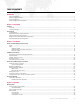
TABLE OF CONTENTS Introduction About This Manual........................................................................................................................................................................ Additional Documentation ............................................................................................................................................................ Customer Service ................................................................................................
Pan/Tilt Screen .................................................................................................................................................................... Information Screen .............................................................................................................................................................. Communication Screen ....................................................................................................................................
INTRODUCTION About This Manual This manual provides necessary information regarding product safety, installation, and operation for the following equipment: + Bad Boy® Spot Luminaire (20.9812.0001) + Bad Boy® CMY Spot Luminaire (20.9812.0002) Familiarizing yourself with this information will help you get the most out of your lighting system. WARNING: It is important to read ALL accompanying safety and installation instructions to avoid damage to the product and potential injury to yourself or others.
Customer Service For technical assistance, contact the PRG International Service Center or contact your nearest PRG office. Contact information for all PRG office locations can be found on our website at: www.prg.com/about-us/locations/ PRG Dallas (International Service) 8617 Ambassador Row, Suite 120 Dallas, Texas 75247 USA Phone: 214.630.1963 Fax: 214.630.5867 Service Fax: 214.638.2125 Service Email: orders@prg.com For additional resources and documentation, please visit our website at: www.prg.
Gobo Art Submission Guidelines 1) Each black and white image should be submitted with artwork oriented as intended for viewing when projected from the luminaire onto a flat surface such as a white wall. 2) Highest resolution and cleanest available image or sketch should be submitted - preferably in vector format (Adobe Illustrator, AutoCad .dxf or .dwg, etc.) or, alternately, a raster image (.tiff, .jpeg, .bmp or .gif) may be used.
Notes 4 BAD BOY® SPOT LUMINAIRE USER MANUAL
1. DESCRIPTION This chapter contains an overview of luminaire features and components.
FEATURES Overview The Bad Boy Spot Luminaire combines the qualities of a traditional automated light with a large venue fixture. Features + Philips MSR Gold™ FastFit lamp that can be set to levels 900W, 1200W, or 1400W. + Built-in LCD touchscreen display which provides access to control, configuration, status, and testing functions. + Zoom lens system consisting of four groups of lenses - each independently controlled for accuracy while maintaining focus during zoom changes.
Luminaire Models The Bad Boy Spot Luminaire is available in two versions: + Standard (20.9812.0001) - contains a Quantum Color® system. + CMY (20.9812.0002) - contains a CMY color system.
COMPONENTS Included Items The following illustration shows all items included with the luminaire: AC Line Cord Power Cable (25.9812.0902.5) (2) Hanging Bracket Assemblies -- with Mega-Claw Truss Hook (21.9812.0863) Bad Boy Luminaire (20.9812.0001) - standard version - or Bad Boy Luminaire (20.9812.0002) - CMY version Figure 1-2: Bad Boy Luminaire Included Items Replacement Items and Accessories The following items can be ordered from PRG. (Please order by PRG part number.) PRG P/N 21.9812.
Major Components and Controls The following illustration shows the external luminaire components and controls. Hanging Bracket Assembly (2) Allows luminaire to be mounted on truss pipe. ACTIVEONLY WHEN FIXTURE IS POWE RED A C IN 200 - 240V A C Upper Enclosure Houses power supply, ballast, and provides Data In and Thru, and AC power connections. Also houses the Menu Touchscreen (see detail below).
Designer Color Wheel Standard Configuration The following drawing shows the standard Bad Boy Designer Color Wheel configuration.
Standard Gobo Wheel Configuration The following drawing shows the standard Bad Boy Designer Gobo Wheel configurations.
Notes 12 BAD BOY® SPOT LUMINAIRE USER MANUAL
2. INSTALLATION This chapter contains instructions for installing the luminaire. It includes instructions for connecting power and data, along with instructions for powering up the luminaire for the first time and addressing it within your system.
POWER AND DATA CABLING REQUIREMENTS Power The Bad Boy Spot Luminaire requires standard AC power distribution from 200-240 VAC, 50/60 Hz, 15A maximum. The upper enclosure provides a Neutrik® connector for power input. Use the provided AC Line Cord Cable Assembly (25.9812.0902.5) to connect power.
The XLR 5-pin connectors should be wired as follows: Pin/Wire Code to XLR Connectors DMX Thru Cable Pinout 1 Pin 2 Pin 3 Pin 4 Pin 5 Foil & Braided Shield 1st conductor of 1st twisted pair 2nd conductor of 1st twisted pair 1st conductor of 2nd twisted pair 2nd conductor of 2nd twisted pair Data (-) Data (+) Data (-) Data (+) 5 2 3 DMX In Cable Pinout Pin 1 4 Male Conn 5 1 4 3 2 Female Conn Note: Refer to the USITT Recommended Practice for DMX512 guide for additional information reg
DMX512 Male Termination Connector A male XLR DMX512 termination connector is required at the last luminaire (or "far end of the line") to prevent signal reflections. Signal reflections may cancel out the signal at certain line lengths, resulting in errors. The terminator is also necessary for software downloads and running tests on multiple luminaires. To construct your own connector, you will need the following components: + 5-pin, male XLR connector. + 120 ohm resistor.
INSTALLATION PROCEDURES Unpacking and Attaching Hanging Brackets The Bad Boy Spot Luminaire can be hung horizontally or vertically from any structure designed to accommodate the load of this moving luminaire. Two provided Hanging Bracket Assemblies (21.9812.0863) are used to attach the luminaire to a truss pipe. The Hanging Brackets consist of a pre-assembled bracket with a Mega-Claw Truss Hook. To unpack and attach brackets: Step 1. Unlatch and remove case lid (Figure 2-2). Step 2.
2-Point Hang 3-Point Hang * * Requires three brackets. Figure 2-3: Hanging Bracket Orientations Standard Hang WARNING: The luminaire is heavy. Use caution when lifting. WARNING: Two safety cables and at least two truss hooks should be used in all hang configurations. To install in standard 2-point hang: Truss Pipe Step 1. Unpack case and attach Hanging Brackets. Refer to "Unpacking and Attaching Hanging Brackets" on page 17. Step 2. Roll case to mounting location as required (Figure 2-4). Step 3.
Step 6. Connect power and data cables according to "Connecting Power and Data" on page 23. Two (2) Safety Cables MUST be used for all hanging installations and may be required by local codes. 30" (762 mm) Safety cables and input pigtail cable must be dressed to avoid interference with luminaire motion. Square tube or round pipe. Minimum outside dimension for pipe or tube is 1 inch (2.54 cm). Maximum outside dimension is 2 inches (5.08 cm) 15.6" (396mm) 39.
Vertical "Yoke Out" Hang The Bad Boy Spot Luminaire can be hung in a vertical position, if required. In this configuration, the luminaire should be positioned so that the interface panel (display) is facing downward for ease of programming. WARNING: The luminaire is heavy. Use caution when lifting. WARNING: The vertical configuration requires 3 people to hang and secure the luminaire. WARNING: Two safety cables and at least two truss hooks should be used in all hang configurations.
Step 6. Feed safety cables through mounting bracket slots and secure around pipe. Step 7. Connect power and data cables according to "Connecting Power and Data" on page 23. 1 Remove Luminaire From Case Vertical Truss 2 Attach to Vertical Truss Wing Bolt a) Using two people, carefully lift luminaire into mounting position so that display is facing downward. b) Using a third person, secure in place by tightening Truss Hook wing bolts.
Standing Position The Bad Boy Spot Luminaire can also be used in a standing position. Be sure that the floor or stage will accommodate the load of this moving luminaire. To install in a standing position: Step 1. Unlatch and remove case lid (Figure 2-8). Step 2. Remove Power Cord and Safety Cables from case. Step 3. Tilt case upright as shown. Use grips on bottom of case to assist in tilting upward. Step 4. Carefully remove luminaire from case and place in standing position. Step 5.
Connecting Power and Data The Bad Boy Spot Luminaire may be controlled by DMX512 or Ethernet. The control inputs are located at the upper enclosure connector panel.
To connect power and data: Step 1. Connect data cable (DMX512 or Ethernet) from console to appropriate input connector at first luminaire in chain (Figure 2-10). Step 2. If required, connect additional data cables from appropriate thru connectors to input connectors of remaining luminaires in chain. Step 3. For DMX512 systems: At last luminaire in chain, install male termination connector at DMX512 THRU connector.
POWER UP AND BASIC SETUP PROCEDURES Powering Up the Luminaire When AC power is applied, the luminaire will begin a calibration sequence which moves its pan, tilt, and all beam control mechanisms. After calibration, the luminaire head will either stop at its "home" position (which positions the pan axis at mid-rotation and the head parallel to the yoke with the lens pointing away from the luminaire upper enclosure) or move to its current DMX-defined position if DMX512 data is present.
Comm LED Operation The Comm LED - located on the upper enclosure connector panel - indicates system control status. This can be used determine if the luminaire is receiving a control signal.
Setting a Starting Address The method for setting a DMX starting address is the same whether the luminaire is being controlled by DMX512 or Ethernet (Art-Net). The only difference is that the Home screen will display the Comm as either "DMX" or "ETH" depending on the control input. The DMX starting address is programmed at the Menu Touchscreen. The luminaire retains its address even if power is removed.
Ethernet (Art-Net) Comm The starting address for Ethernet (Art-Net) systems is programmed using the CONFIG menu. To program a starting address: Step 1. At Home screen, press CONFIG panel. Step 2. At Configuration screen, press DMX ADDRESS panel. Step 3. At numeric keypad, enter new starting address and press ENTER. Control Input Type Figure 2-14: Setting Starting Address (Ethernet Control) To select an Art-Net universe: If using Ethernet control, a universe must be selected in addition to the DMX address.
Starting the Lamp The lamp can be started (turned on) via console command or at the luminaire itself by using the Menu Touchscreen. To start lamp using Menu Touchscreen: Step 1. At Home screen, press LAMP panel. Step 2. At Lamp screen, current lamp status (ON/OFF) will be displayed. Press START to bring up YES/NO options. Figure 2-16: Starting the Lamp Step 3. Press YES to start lamp.
Configuring Comm Loss Setting The Communication screen includes a "Comm Loss" setting. This setting will configure how long to wait before the fixture fades to black upon loss of comm data. To configure the Comm Loss setting: Step 1. At Communication screen, press COMM LOSS. Step 2. Set Trigger Fade After to none, 30 seconds or 60 seconds. Step 3. Exit Communication screen.
ACCESSORY OPTIONS Follow Spot Operation The Bad Boy Spot Luminaire may also be used as a follow spot fixture. A Follow Spot Handles Kit (28.9812.0688) is available for this purpose. The kit includes three handles so that follow spot operation may be accomplished from the side of the fixture (using the two side handles) or from the rear of the fixture (using the two rear handles).
Step 3. For each Handle Assembly, feed Lanyard through yoke handle, then feed Handle through loop as shown in Figure 2-19. Step 4. Thread Handles into Handle Mounts. Lanyard Yoke Handle Follow Spot Handle Assembly Figure 2-19: Installing Follow Spot Handles - Step 2 Enabling Pan/Tilt Free Mode At Pan/Tilt Menu: A "Free" mode is available at the Pan/Tilt Menu screen so that the luminaire may be used as a follow spot fixture. The FREE panel displays the current "free" setting.
3. OPERATION This chapter contains instructions for using the Menu Touchscreen and controlling the luminaire by DMX512.
MENU SYSTEM Using the Menu Touchscreen The menu system is a set of software screens used to configure, address, report status, and test the luminaire. These functions are controlled at the Menu Touchscreen as shown in Figure 3-1. LAMP temp COMM Menu Touchscreen Used to configure luminaire address and other options. Also, provides status information and testing.
LAMP temp COMM ACTIVE ON LY WHE N FIXTURE IS POW ERED INFO hrs 125 34C 01:34 THRU CONFIG addr univ AC IN 200 -240 VAC TEST 1400w COMM 043 A DMX DMX ETHERNET STATUS OK IN 50 / 60 Hz 15A Max Battery Wake Switch * * Not available on all units Figure 3-2: Battery Wake Switch Note: The Battery Wake Switch is not available on all units.
Menu System Overview The menu system consists of a hierarchy of menu levels as shown in Figure 3-3. Sub-menus, options, and alpha/numeric keypads may be accessed by pressing the blue and red areas of these main screens. Pressing EXIT will return to the previous screen. When power is applied to the luminaire, the Menu Touchscreen will display an initialization screen during calibration. After calibration is complete, the Home screen will be displayed.
Menu Details Home Screen The Home screen consists of several sections (referred to here as "panels") which provide status and configuration information. Pressing the panels on the touchscreen will open the applicable sub-menus. LAMP Panel + Lamp Status - displays lamp on/off status, hours, temperature and power level. The lamp icon color indicates status of lamp: off = gray icon, on = yellow icon (shown in example at right), error = red icon. + Power Level - displays current APS command: 700-1400 watt.
Lamp Screen + Lamp Hours- displays total lamp hours. Lamp hours are shown in green if under threshold, yellow at 750 hours, and red at 900 hours. It is mandatory that the lamp be changed before 900 hours. Press to bring up Reset Lamp Hours Yes/No options. + Strikes - displays number of times the lamp has been struck. + Max Power - sets maximum power limit. Press to bring up 900/1200/1400 options. (This setting is also accessible from the Control Channel. Refer to page 45.
Default Settings: + Address: 001 + P/T: unlocked + Lamp Setting: 1400W + Universe: A + P/T: standard (not inverted or swapped) + Lamp Power Up: wait + Universe Setting: alpha + Zoom: normal + Display: auto Pan/Tilt Screen + Invert Pan / Invert Tilt - displays current invert settings. Press to bring up Invert Yes/No options. When inverted, pan/tilt will move in the opposite direction. + Swap - displays current swap setting. Press to bring up Swap Pan/Tilt Yes/No options.
Communication Screen + Control - displays current DMX512 control values. Values will be highlighted in green when changing. + Info - displays current source (DMX512 or Art-Net/Ethernet), number of bytes in the frame, update rate, and universe number (if Art-Net). + Comm Loss - configures how long to wait before the fixture fades to black upon loss of comm data. Press COMM LOSS to bring up "Set Trigger Fade After" option. Set to none, 30 seconds or 60 seconds.
Test Screen + Re-Cal - press to bring up Recalibration Screen. (During recalibration, intensity goes out until all mechanism calibrations are complete and back in position, then fades in.) + Re-Call ALL - press to bring up Re-Cal ALL Yes/No options. + Disable - press to bring up Disable Screen. + Mech Test - press to bring up Mechanical Test Screen. (See "Mechanical Test" on page 57 for more explanation of this screen.
DMX512 OPERATION Channel Mapping Table 3-1: DMX512 Channel Mapping Channel 1 2 3 4 5 6 7 8 9 10 11 12 13 14 15 16 17 18 19 20 21 22 23 24 25 26 27 28 29 30 31 32 33 34 35 36 37 38 39 40 41 42 42 Function Intensity - Hi Byte Intensity - Lo Byte Pan - Hi Byte Pan - Lo Byte Tilt - Hi Byte Tilt - Lo Byte Cyan - Hi Byte Cyan - Lo Byte Cyan Control Yellow - Hi Byte Yellow - Lo Byte Yellow Control Magenta - Hi Byte Magenta - Lo Byte Magenta Control Designer - Hi Byte Designer - Lo Byte Designer Control Gobo1 - H
Wheel Control Every wheel, gobo or color, as well as the gobos within a wheel, follow the exact same method of control. Select the mode with the associated control channel: continuous [index], discrete [step], spin, random slow, medium, and fast, with strobe range at the end. The preceding 16-bit channel sets either your choice (a gobo or color in continuous, discrete, or strobe modes, indexed position for gobos), or your rate (spin/gobo rotation).
The diagram below illustrates the wheel control modes, using the standard Color Wheel as an example: Control Channel Wheel Channel 0-9 continuous wheel choice Continuously adjustable throughout the range. 0 57344 49152 8192 40960 16384 24576 32768 10-19 discrete Discrete positions of whole and half slots. direction/speed CCW 3276965535 20-39 spin Stop 3276732768 Endlessly spins in a clockwise or counterclockwise direction.
Control Channels All Control Channel functions require that the specified DMX value be held for at least 3 seconds, followed by an immediate change to DMX 0 (without any other DMX values in between). Zoom tables are dependent on distance to target, so several tables are provided to allow focus zoom at different throws.
Timing Channels Channel Functions Timing channel control improves the timed moves of certain groups of parameters. Three timing channels are provided: one for Focus (Pan and Tilt), one for color parameters and one for beam parameters. Timing channels support time values of up to six minutes.
Table 3-8: Timing Channels % Value 1 2 3 4 5 6 7 8 9 10 11 12 13 14 15 16 17 18 19 20 DMX 0 1 2 3 4 5 6 7 8 9 10 11 12 13 14 15 16 17 18 19 20 21 22 23 24 25 26 27 28 29 30 31 32 33 34 35 36 37 38 39 40 41 42 43 44 45 46 47 48 49 50 51 = Seconds Full Speed 0.2 0.4 0.6 0.8 1 1.2 1.4 1.6 1.8 2 2.2 2.4 2.6 2.8 3 3.2 3.4 3.6 3.8 4 4.2 4.4 4.6 4.8 5 5.2 5.4 5.6 5.8 6 6.2 6.4 6.6 6.8 7.0 7.2 7.4 7.6 7.8 8 8.2 8.4 8.6 8.8 9 9.2 9.4 9.6 9.8 10 10.
Table 3-8: Timing Channels (Continued) % Value 41 42 43 44 45 46 47 48 49 50 51 52 53 54 55 56 57 58 59 60 61 48 DMX 105 106 107 108 109 110 111 112 113 114 115 116 117 118 119 120 121 122 123 124 125 126 127 128 129 130 131 132 133 134 135 136 137 138 139 140 141 142 143 144 145 146 147 148 149 150 151 152 153 154 155 156 157 = Seconds 31 32 32 32 33 33 34 34 34 35 35 36 36 36 37 37 38 38 38 39 39 39 40 40 41 41 41 42 42 43 43 43 44 44 45 45 45 46 46 47 47 47 48 48 49 49 49 50 50 50 51 51 52
Table 3-8: Timing Channels (Continued) % Value 83 84 85 86 87 88 89 90 91 92 93 94 95 96 97 98 99 100 DMX 211 212 213 214 215 216 217 218 219 220 221 222 223 224 225 226 227 228 229 230 231 232 233 234 235 236 237 238 239 240 241 242 243 244 245 246 247 248 249 250 251 252 253 254 255 = Seconds 150 150 160 160 160 170 170 180 180 180 190 190 200 200 200 210 210 210 220 220 230 230 230 240 240 250 250 250 260 260 270 270 270 280 280 290 290 290 300 300 310 310 310 310 Follows Cue Data BAD BOY® SP
Zoom Tables The zoom tables, which allow the fixture to maintain sharp focus on an image throughout the zoom range, are sensitive to the throw distance. For this reason, a variety of zoom table versions are available for use with different throws. The zoom table is selectable via control channel settings described in "Control Channels" on page 45. The zoom table setting is persistent and will maintain its value through power cycles. The default setting is 30 feet.
4. TROUBLESHOOTING AND MAINTENANCE This chapter provides a basic troubleshooting guide, along with procedures for testing, proper handling, and routine maintenance.
TROUBLESHOOTING Troubleshooting Guide The following table provides a list of common start-up problems and possible solutions. Symptom Solution(s) Refer to... Ensure power cable is properly connected to Neutrik input connector. page 14 Ensure power is switched on at source (mains, disconnect box, etc.) n/a Ensure DMX512 or Ethernet data cable is properly connected. page 23 Ensure DMX512 address setting is correct. page 27 Ensure data cables are correctly configured.
Errors The Status menus can be used to determine if any luminaire mechanisms are reporting errors. The Status panel at the Home screen will report overall luminaire conditions as follows: + CALIBRATION (yellow) + OK (green) + ERROR (red) + LOCKED (white) Press STATUS to bring up Status screen Pressing the Status panel will bring up the Status screen (as shown at right). The Status screen will indicate which specific mechanisms, if any, have errors. It also provides a log of systems activity.
Mechanism Errors Errors will be shown after the mechanism code, for example: PAN:Comm Error.
Other Errors Error Code Explanation Solution Temp over threshold Temperature too high Check fans/filters Lamp over threshold Lamp hours above recommended maximum Change lamp Lamp Off Fan Error: Cannot strike lamp while any fan is in error state Check fan, fan cabling Pan/Tilt Aux Encoder Error Auxiliary encoder value is too far from the main encoder value Check auxiliary encoder and cabling/connections Gobo out of zero range When zeroing gobo wheels, the wheel is too far away from zero to se
TESTING Test Screen + Re-Cal - press to bring up Recalibration Screen. + Re-Call ALL - press to bring up Re-Cal ALL Yes/No options. + Disable - press to bring up Disable Screen. + Mech Test - press to bring up Mechanical Test Screen. (See "Mechanical Test" on page 57 for more explanation of this screen.) + Clean Lenses - press to position lenses so that all surfaces may be cleaned with a cloth. (Note that pressing the button does not actually clean the lenses.
Mechanical Test The Mechanical Test menu provides a method for exercising all luminaire mechanisms individually. Each mechanism has a similar Test screen, Cyan is shown in the example below: The following test functions are available: + Test Chase - The mechanism will move back and forth between two positions. The START/STOP button starts and stops the motion, and the SPEED button sets the rate of the motion.
Group Test The Group Test menu allows multiple Bad Boy Luminaires to be run through a configurable test sequence when chained together via DMX512 or Ethernet. (Refer to "Connecting Power and Data" on page 23 for more information about daisy-chaining.) To perform a group test: Step 1. At Group Test screen, select options to run: Pan/Tilt, Intensity, Colors, Gobos, and/or Zoom. Step 2.
SOFTWARE UPDATE Software Update Using LumLoader Application Introduction The LumLoader application allows you to update the software in a Bad Boy Luminaire. The update will be sent over an Ethernet connection. The luminaire can take the Ethernet input directly, or the update can be translated to DMX512 signal with an appropriate device, either Series 400® or a Virtuoso® Node (with the required software update). The fixtures can be daisy-chained to load multiple fixtures at once.
Troubleshooting + If the LumLoader application does not start up, make sure the Java library is installed. + Make sure the network port is active before starting the application. Sometimes it takes several seconds for the operating system to recognize the network link. + Make sure there is only one instance of the LumLoader application running. + Wireless should be disabled on the computer.
EQUIPMENT HANDLING Proper Lamp Servicing and Operation Servicing + When handling a lamp, hold it by the ceramic base while wearing cotton gloves or finger cots. Do not touch the glass envelope (bulb). If you touch the glass with bare fingers, wipe off any fingerprints with alcohol. Heat + When lamps are lit, the interior of the luminaires becomes very hot. To aid in the airflow circulation within the luminaires, after dousing the lamps, wait 5 minutes before removing power to the luminaires.
ROUTINE MAINTENANCE Removing the Head Covers To access some interior head components, one or both of the Head Covers may need to be removed. Parts: 21.9812.0630 2 EA ASSY, HEAD COVER Tools: #2 Philips screwdriver (manual screwdriver only) To remove Head Covers: Step 1. At Head Cover, remove two 8-32 x 3/8" PPB screws (Figure 4-1). Step 2. Remove Head Cover from luminaire. R2 / Designer Wheel Head Cover Aft Cover Front Ring Casting 8-32 x 3/8" PPB Screw (2 ea) R1 Head Cover Hand tighten only.
Removing the Aft Cover To access some interior head components, the Aft Cover may need to be removed. Parts: 21.9812.0612 1 EA ASSY, AFT COVER w/ BAFFLE Tools: 5/32" Allen wrench, T-bar To remove Aft Cover: Step 1. At Aft Cover, remove X, Y, and Z Adjustment Knobs (Figure 4-2). Step 2. Remove four 10-32 x 3/8" socket head screws. Step 3. Carefully remove Aft Cover from luminaire.
Removing the Enclosure Covers To access interior enclosure components, one or both of the Upper Enclosure Covers may need to be removed. Parts: 21.9812.0820 21.9812.0830 1 EA 1 EA ASSY, INTAKE COVER, UPPER ENCLOSURE ASSY, EXHAUST COVER, UPPER ENCLOSURE Tools: #2 Philips screwdriver To remove Upper Enclosure Covers: Step 1. At Upper Enclosure Cover, loosen two captive screws. Step 2. Remove cover by pulling straight out until lip clears yoke support. CAUTION: The Upper Enclosure Covers are not identical.
Cleaning the Head Electrostatic Filters The electrostatic filters should be cleaned or replaced when they are dirty. The frequency will depend on how often and in what conditions the luminaire is used. Tools: #2 Phillips screwdriver Compressed air and/or water Parts: 10.9812.0661 10.9812.0662 2 EA 2 EA HEAD AIR FILTER FOAM HEAD AIR FILTER ELECTROSTATIC To clean head filters: WARNING: Remove power from luminaire before performing any maintenance procedures. Step 1. Remove power from luminaire. Step 2.
Cleaning the Enclosure Intake Filters The intake filters should be cleaned or replaced when they are dirty. The frequency will depend on how often and in what conditions the luminaire is used. Tools: #2 Phillips screwdriver Compressed air and/or water Parts: 40-9812-0834 2 EA AIR INTAKE FILTER To clean enclosure intake filters: WARNING: Remove power from luminaire before performing any maintenance procedures. Step 1. Remove power from luminaire. Step 2.
Cleaning the Luminaire Exterior Tools: Lint-free cloth Window cleaner Vacuum cleaner with brush nozzle or compressed air #2 Phillips screwdriver To clean luminaire: WARNING: Remove power from luminaire before this procedure. CAUTION: Use ONLY OptiMax™ Ultra Pure Cleaning Solution to clean optical components. DO NOT use Window Cleaner on lens! Step 1. Remove power from luminaire. Step 2. Using vacuum cleaner with brush nozzle or compressed air, clean dust from external components.
Cleaning the Lenses Tools: (2) Micro Fiber cloths (06.6085.0001.0) OptiMax™ Ultra Pure Cleaning Solution (06.6084.0001.0) Cotton gloves or finger cots #2 Phillips screwdriver Hook & Pick tool To clean lenses: CAUTION: Use caution when handling lenses. Avoid scratching optical surfaces. CAUTION: Use ONLY OptiMax™ Ultra Pure Cleaning Solution to clean optical components. DO NOT use Window Cleaner on lenses! Wear cotton gloves or finger cots when handling lenses/glass. Step 1.
d. Using OptiMax™ Ultra Pure Cleaning Solution and a Micro Fiber cloth, clean both sides of Front Glass and front of Lens Group 4. DO NOT use window cleaner! e. Re-install Front Glass. Notch Front Glass Retaining Ring Front of Lens Group 4 Figure 4-6: Removing Front Glass CAUTION: "Done" MUST BE pressed at the menu to complete the procedure. If the lens motors are left in the cleaning configuration for too long, they may be damaged due to overheating. Step 9. At menu, press "Done.
Hand tighten only. DO NOT use a CAUTION: power tool on Head Cover screws.
Cleaning Gobo, Color and Dimmer Wheels Tools: Micro Fiber cloth (06.6085.0001.0) OptiMax™ Ultra Pure Cleaning Solution (06.6084.0001.0) Cotton gloves or finger cots #2 Phillips screwdriver To clean gobo, color and dimmer wheels: CAUTION: Use ONLY OptiMax™ Ultra Pure Cleaning Solution to clean optical components. DO NOT use Window Cleaner on gobo, color, or dimmer wheels! Wear cotton gloves or finger cots when handling optical components.
Replacing the Lamp Parts: 71.2566.1200.0 1 EA LAMP, FASTFIT, PHILIPS MSR GOLD™ Tools: Cotton gloves or finger cots WARNING: Remove power from luminaire before performing any maintenance procedures. CAUTION: Refer to "Proper Lamp Servicing and Operation" on page 61 before handling the lamp. To replace lamp: Step 1. Remove power from lamp and allow lamp to cool for at least 5 minutes. Step 2. Remove power from luminaire. Step 3.
CAUTION: Wear cotton gloves or finger cots while servicing lamp. Touching the lamp glass with bare fingers will leave oil and cause the lamp to explode or burn out early. If touched, use alcohol to thoroughly clean glass. CAUTION: Do not touch lamp or reflector with bare fingers. CAUTION: Allow lamp to cool before servicing. Backcap Lamp Base Lamp DETAIL A: LAMP ORIENTATION Turn 45° Clockwise. Base will click when properly seated.
Adjusting the Lamp After a new lamp is installed, it will be necessary to align the lamp in order to center and flatten the hot spot. Knobs located at the luminaire’s backcap allow for adjustment. Tools: none WARNING: Backcap may be HOT during lamp operation. To adjust lamp: Step 1. Power up luminaire and allow to warm up for at least ten minutes. Step 2. Set intensity to 100%. Step 3. Position beam on a white wall at a distance of 10' to 20'. Step 4.
Replacing a Gobo Parts: Standard or Custom Gobo(s), as required. (Refer to "Standard Gobo Wheel Configuration" on page 11.) Tools: #2 Phillips screwdriver Cotton gloves or finger cots WARNING: Remove power from luminaire before performing any maintenance procedures. To replace a gobo: Step 1. Remove power from luminaire. Step 2. Locate appropriate head cover door for access to Rotating Gobo Wheel 1 (R1) or Rotating Gobo Wheel 2 (R2) as shown in Figure 4-10. (Doors are identified by a label.
Step 5. Using fingers, grasp frame of gobo and pull out of wheel (Figure 4-11). Sun Gear Retaining Plate Gobo Carrier Tab 3 Tongue Locking Tab 2 4 1 Open Hole (no gobo) 5 6 7 Wheel Note: Drawing is flipped 180° for clarity purposes. Figure 4-11: Replacing a Gobo Step 6. Noting proper orientation, insert new gobo into wheel. Ensure that the "tongue" of the gobo clip goes under the retaining plate (under the sun gear).
OPEN 1 OPEN 7 2 1 6 3 7 2 5 6 3 5 4 4 OPEN 1 7 2 6 3 2 5 4 CAUTION: The gobos must be seated properly, especially the gear mesh.
Replacing a Designer Color Filter Parts: Designer Color Filter(s), as required. (Refer to "Designer Color Wheel Standard Configuration" on page 10.) Tools: #2 Phillips screwdriver Cotton gloves or finger cots WARNING: Remove power from luminaire before performing any maintenance procedures. To replace a designer color filter: Step 1. Remove power from luminaire. Designer Color Filter Step 2. Locate appropriate head cover door for access to Designer Color Wheel as shown in Figure 4-10 on page 75.
4 5 3 6 2 7 1 OPEN EXPLODED VIEW Figure 4-14: Installing Designer Color Filter BAD BOY® SPOT LUMINAIRE USER MANUAL 79
Notes 80 BAD BOY® SPOT LUMINAIRE USER MANUAL
A. TECHNICAL SPECIFICATIONS + BAD BOY SPOT LUMINAIRE + BAD BOY ROAD CASE + AC LINE CURRENT / POWER VS.
Bad Boy Spot Luminaire SOURCE: Philips MSR Gold™ 1200W FastFit Lamp. Can be set to levels 900W, 1200W, or 1400W. OUTPUT: 48,000 lumens OPTICAL EFFICIENCY: 40% REFLECTOR: Precision glass reflector with dichroic cold mirror coating. OPERATING TEMP: -20° to 120°F (-29° to 49°C) COOLING: Forced air. CONTROL: Compatible with all PRG consoles and a wide variety of DMX512 and Art-Net consoles. An internal Ethernet switch allows for daisy-chaining fixtures.
30" (762 mm) 15.6" (396mm) 39.125" (994 mm) POSITIONING: Can be mounted in any orientation. SPACING: 13.5" (343 mm) Hangs on 30 inch (762 mm) centers. WEIGHT: 167 lbs (75.
Bad Boy Road Case EMPTY WEIGHT: 190 lbs (86.18 kg) LOADED WEIGHT: 357 lbs (161.93 kg) - includes (1) one luminaire with clamps and rails 30.
AC Line Current / Power vs. Voltage TEST VOLTS FREQ AMPS VA POWER PF 1 170 50Hz 10.27 1746 1735 0.998 2 180 50Hz 9.62 1732 1721 0.995 3 200 50Hz 8.56 1712 1713 0.994 4 200 60Hz 8.57 1714 1709 0.996 5 210 60Hz 8.16 1714 1707 0.997 6 220 50Hz 7.77 1709 1704 0.991 7 230 50Hz 7.47 1718 1708 0.998 8 240 50Hz 7.14 1714 1705 0.993 9 240 60Hz 7.16 1718 1702 0.996 10 250 50Hz 6.83 1708 1704 0.992 11 260 50Hz 6.62 1721 1701 0.
Narrow Zoom Iris Full Open 8º Full Angle 40,000 beam Lumens Throw Dist (Ft) 20 30 50 75 100 Beam Dia. (Ft) 2.8 4.2 7.0 10.5 14.0 12095 5376 1935 860 484 Illuminance (fc) Throw Dist (m) Beam Dia. (m) Illuminance (lux) 5 10 20 25 30 0.7 1.4 2.8 3.5 4.2 193520 48380 12095 7741 5376 Multiply throw distance by Tn to find beam diameter. Divide cd (candela) by distance squared to find center beam illuminance. Dist. in Ft. = foot candles Dist. in meters = lux 5000000 Tn = 0.
Medium Zoom Iris Full Open 34º Full Angle 48,000 beam Lumens Throw Dist (Ft) 20 30 50 75 100 Beam Dia. (Ft) 12.2 18.3 30.6 45.9 61.1 Illuminance (fc) 850 378 136 60 34 Throw Dist (m) 5 10 20 25 30 3.1 6.1 12.2 15.3 18.3 13600 3400 850 544 378 Beam Dia. (m) Illuminance (lux) Multiply throw distance by Tn to find beam diameter. Divide cd (candela) by distance squared to find center beam illuminance. Dist. in Ft. = foot candles Dist. in meters = lux 350000 Tn = 0.
Wide Zoom Iris Full Open 56º Full Angle 50,000 beam Lumens Throw Dist (Ft) 20 30 50 75 100 Beam Dia. (Ft) 21.3 31.9 53.2 79.7 106.3 Illuminance (fc) 312 139 50 22 12 Throw Dist (m) Beam Dia. (m) Illuminance (lux) 5 10 20 25 30 5.3 10.6 21.3 26.6 31.9 5000 1250 312 200 139 Multiply throw distance by Tn to find beam diameter. Divide cd (candela) by distance squared to find center beam illuminance. Dist. in Ft. = foot candles Dist. in meters = lux 130000 120000 Tn = 1.
Logarithmic Beam Illuminance Comparison 8º, 34º and 56º Zoom settings. (DMX Values 00000, 30192, & 57700) 10000000 WFOV MFOV NFOV 1000000 Candela 100000 Lamp Power = 1400 Watts -30.0 -20.0 -10.0 0.0 Deg. 10.0 20.0 30.
Notes 90 BAD BOY® SPOT LUMINAIRE USER MANUAL
B. GLOSSARY This glossary provides useful terms associated with operating Bad Boy Spot Luminaires.
Glossary of Terms Address A numerical "name" given to a device on a DMX512 line indicating which of 512 possible channels it will respond to. Align (lamp) The process of adjusting the lamp within the reflector to obtain the desired output quality of the beam. Arc Lamp A type of lamp which creates light by forming an arc of electricity. Brightness is achieved by including gasses and metals within the envelope of the lamp which dissolve and give off a bright light.
Fixture Orientation Based on the direction the pigtail points as it exits the fixture. Flipped Focus When one or more fixtures inadvertently move differently from others in the system. Focus The point to which the light beam is directed. Also, a function of the luminaire related to the direction of the beam as specified by pan and/or tilt data. Follow Spot When the luminaire is manually moved using the optional follow spot handles and pan/tilt Free mode in order to function as a spot light.
Signal Control protocol from a lighting console or interface. Show File A file containing all programmed cue data. Splitter (Isolator) Device used to optically isolate and split a DMX512 signal. Note: A DMX "two-fer" cannot be used to divide a signal. Start To energize a luminaire arc lamp (applies to arc-lamp luminaires only). Strobe A special lighting effect which produces multiple rapid bursts of high intensity light.
Bad Boy® Spot Luminaire User Manual Version as of: January 5, 2011 PRG part number: 02.9812.0001.
Production Resource Group Dallas Office 8617 Ambassador Row, Suite 120 Dallas, Texas 75247 www.prg.