
Reference Guide 5.4 Owner manual

DMX512 REFERENCE GUIDE 73
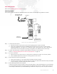
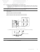
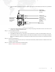
Series 200 Luminaires
Refer also to "DMX512 System Example" on page 7.
Connecting to System
Series 200 luminaires will require a DMX200 interface unit in order to control them from DMX512 consoles.
Figure 3-25: Series 200 System Diagram
Step 1. Locate house AC service.
a. Determine location of main power service where lighting system will be connected.
b. Verify with a qualified electrician (see WARNING above) that house AC service is within system
operating voltages: 85 - 130 VAC or 170 - 260 VAC, single or three phase, 50 or 60 Hz. Ensure that
house service can accommodate connecting 2/0 pig tails or 8/5 cables to house service lugs.
Step 2. Position ACS, Mini-ACS, or SixPack chassis delta/we switches to correct setting.
Refer to "Configuring Equipment For Delta or Wye Operation" on page 19.
Step 3. Tie in 2/0 or 8/5 tails.
a. Remove power from house service or verify that service disconnect switch is in the OFF position.
b. Have a qualified electrician connect 2/0 or 8/5 pig tails to house service.
Step 4. Attach line disconnects to pig tail cable.
a. Verify circuit breaker is in "off" position before installing line disconnect(s).
b. Connect line disconnect(s) to end of AC tails (2/0 or 8/5). (Line disconnects should be easily accessible
in case emergency requires shutting off power to system.)
Step 5. Attach Bucking Transformer (if required).
If house AC service is below 100 VAC or above 240 VAC (Europe, Japan and Australia), it may be necessary
to connect Bucking Transformer between pig tails and lighting system ACS or modular racks to reduce or
raise voltage to desired level. (A standard Bucking Transformer accepts only Cam-Lok style connectors.)
DMX200 Translator
Y Cable
INPUT
ACS Rack
OUTPUT
INPUT
OUTPUT
Series 200
Lamp Cable
Data & Power
Series 200
Trunk Cable
Data & Power
Series 200 luminaires
VL2B/VL2C, VL4
DMX200 Unit
S200
Repeater
Data & Power
XLR DMX Data Cable
from DMX512 source.
Power from
Modular Rack