SOFTWARE VERSION 1.12 WWW.PRG.
AutoPar®, Bad Boy®, PRG Series 400®, Mbox Extreme®, OHM™, V476™, V676™, Virtuoso®, Virtuoso® DX, Virtuoso® DX2, and VL6C+™ are trademarks of Production Resource Group, LLC, registered in the U.S. and other countries. Gekko kleer colour® logo and Gekko kleer colour technology are trademarks of Gekko Technology Limited. All other brand names which may be mentioned in this manual are trademarks or registered trademarks of their respective companies.
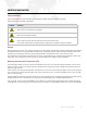
IMPORTANT INFORMATION Safety Information The symbols below are used throughout this manual to identify important safety information. Heed all warnings and safety information. SYMBOL MEANING Warning, Danger or Caution Risk of injury to yourself or the product. Risk of Electrical Shock Risk of severe electrical shock. Risk of Electrical Shock. No serviceable parts inside. Observe all local and national electrical and environmental codes.
TABLE OF CONTENTS Introduction About This Manual........................................................................................................................................................................ 3 Additional Documentation ............................................................................................................................................................ 3 Customer Service ............................................................................................
INTRODUCTION About This Manual This manual provides installation, operation, and maintenance instructions for the OHM™ Light. This manual applies to the following software versions: + MMI: 1.12 + Driver Board: 1.08 Familiarizing yourself with this information will help you get the most out of your PRG product. Additional Documentation For more information regarding DMX512 systems, refer to the DMX512/1990 & AMX 192 Standards publication available from United States Institute for Theatre Technology, Inc.
Customer Service For technical assistance, contact the PRG International Service Center or contact your nearest PRG office. Contact information for all PRG office locations can be found on our website at: www.prg.com/about-us/locations/ PRG Dallas (International Service) 8617 Ambassador Row, Suite 120 Dallas, Texas 75247 USA Phone: 214.630.1963 Fax: 214.630.5867 Service Fax: 214.638.2125 Service Email: orders@prg.com For additional resources and documentation, please visit our website at: www.prg.
USER INSTRUCTIONS General Notes 1) Please read through this manual carefully before operating the OHM Light. Keep this manual for future reference. 2) There are numerous safety instructions and warnings that must be adhered to for your own safety. 3) OHM is not intended for residential use. It is only intended for use in a professional studio. 4) OHM must only be serviced by a qualified individual. 5) OHM is rated as IP20 - for indoor use and in a dry environment.
Additional Safety Considerations 1) Do not open OHM when the fixture is powered. 2) Allow OHM to cool before servicing, as internal parts may be hot. 3) Do not alter the design of OHM or tamper with any of the safety features. 4) Do not look directly into OHM's bare light source as it may be harmful to the eyes. 5) OHM reaches a maximum surface temperature of 85ºC. Please ensure contact on the surface by persons or materials is avoided when the fixture is operating.
FIXTURE OVERVIEW OHM Components and Controls OHM is a powerful light fixture that incorporates sixteen of Gekko's high quality, kleer colour® LED arrays. This LED source provides the user with a large volume of white light at a stable and repeatable CCT, emulating traditional sources. The OHM Light can be controlled via the MMI (Man-Machine Interface) attached to the side of the fixture, or via an external DMX512 that can communicate with the fixture through a control port located on the local controls.
SPARE PARTS/ACCESSORIES Individual Parts List The following is a list of PRG accessory and replacement parts available for OHM: CODE ITEM Complete Kits: 757-300100 PRG OHM Light Fixture 757-300110 PRG OHM Hanger Assembly (Four Cables Included) Mounting and Suspension: 757-300465 PRG OHM Spigot 28mm, Anti-Rotate w/Screw 757-300470 PRG OHM Lifting Eye, M12 757-300610 PRG OHM Hanger Frame 757-300615 PRG OHM Hanger Frame Cable Mounting Options Yoke [1] Locking Handle - turning counter-clockwise l
Spigot/Lifting Eye [1] 28mm Spigot - used to fix OHM into a 28mm receiver. [2] M12 Lifting Eye - used to hang OHM from a single point. 1 [3] M12 x 1.5mm, 25mm Long Bolt - used to bolt either the Spigot or the Lifting Eye to OHM. 2 3 NOTE: tighten M12 bolt to 85Nm (63lbft). Use minimum 8.8 grade bolt. Hanger Assembly (Used to hang OHM from four points.
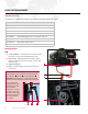
Powering Options Neutrik Power Cable Connector OHM is fitted with a Neutrik PowerCon® NAC3 type connector. Use only Neutrik PowerCon NAC3FCA connectors. ENGAGEMENT It is the user's responsibility to provide and wire their own power cable using the Neutrik power cable connector provided with OHM. To wire connector: Step 1. Slide bushing and chuck onto cable. Step 2. Prepare cable as shown in Figure 1. Step 3. Insert wire into terminals and fasten clamping device using slotted screwdriver.
OPERATION OHM provides control over the Intensity and CCT (Correlated Color Temperature). These variables can be controlled directly from the MMI located on the side of the fixture, or via DMX. Connection Ports Connections are as follows: [1] Comms Port: This port allows for software updates. [2] DMX In: Data in via DMX512 protocol. [3] DMX Thru: Data out via DMX512 protocol. 1 2 3 [4] Power In (AC): The Neutrik power cable will connect to OHM via this port.
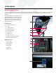
Default Control Screen: [1] Rotary Knob: Alters the intensity of the set CCT from 0%-100%. 3 4 [2] Black Button: Switches the light source OFF (NOTE: the MMI remains ON). W h i t e 2 9 0 0 K [3] Grey Button: Currently disabled. [4] Blue Button: Currently disabled. O N C C T S t u d i o 1 0 0 % D M X 4 5 1 M E N U [5] Red Button: Accesses the 1st level menus. 2 1 5 The Man-Machine Interface (MMI) consists of numerous menus that control the fixture.
Navigation Through '1st Level' Menus W h i t e 2 9 0 0 K O N C C T S t u d i o 1 0 0 % D M X 4 5 1 M E N U 1 C o l o u r C C T S E L E C T 2 C o l o u r G e k k o SCROLL S E L E C T 3 D M X A d d r e s s S E L E C T 4 D M X M o d e S E L E C T 5 I n f o r m a t i o n S E L E C T NOTE: 2 clicks are required to cycle back to the initial control screen 6 M a i n t e n a n c e S E L E C T OHM™ LIGHT USER MANUAL 13
Navigation Within 'Color CCT' Menu Once the required CCT is selected, the corresponding control screen will open. This example shows the 2900K CCT control screen. 1 W h i t e 2 9 0 0 K O N C C T S t u d i o 1 0 0 % D M X 4 5 1 C o l o u r M E N U S E L E C T C o l o u r C C T 2 9 0 0 K S t u d i o S E L E C T M E N U C o l o u r C C T 3 2 0 0 K T u n g s t e n S E L E C T M E N U Continuous scrolling will show every option.
Navigation Within 'Color Gekko' Menu Once the required CCT is selected, the corresponding control screen will open. This example shows the 2900K CCT control screen. 2 G e k k o g e l 1 2 3 H L D S p e c i a l s t e e l b l u e O F F 5 0 % D M X 1 2 3 C o l o u r G e k k o S E L E C T M E N U G e k k o g e l 1 2 3 S p e c i a l s t e e l b l u e S E L E C T M E N U Continuous scrolling will show every programmed Gekko colour. Note: This menu is empty upon delivery of OHM.
Navigation Within 'DMX Mode' Menu Once the required DMX Mode is selected, the current control screen will re-open. This example shows the 2900K CCT control screen. 4 W h i t e 2 9 0 0 K O N C C T S t u d i o 1 0 0 % D M X 4 5 1 D M X M E N U M o d e S E L E C T D M X M o d e S t a n d a r d S E L E C T M E N U D M X M o d e A d v a n c e d S E L E C T M E N U Navigation Within 'Information' Menu If any button is pressed, the current control screen will re-open.
Navigation Within 'Maintenance' Menu If any button is pressed, the current control screen will re-open. This example shows the 2900K CCT control screen. 6 W h i t e 2 9 0 0 K O N C C T S t u d i o 1 0 0 % D M X 4 5 1 M a i n t e n a n c e M E N U S E L E C T M a i n t e n a n c e When the Maintenance option is selected, OHM functions in Maintenance Mode. This mode allows the connection to the internal electronics via use of the Communications Port.
Depending on the DMX Mode assigned through the MMI the DMX controls are as follows: OHM - 'Standard' DMX Control (2 Channels) + DMX Channel 1 = Master Intensity (DMX value 0-255 = level 0-100%) + DMX Channel 2 = CCT Color Wheel: 2900K 3200K 3600K 4300K 5000K 5600K 6500K 0 37 75 110 146 182 218 - - - - - - - 36 74 109 145 181 217 255 OHM DMX OHM - 'Advanced' DMX Control (10 Channels) + DMX Channel 1 = Master Intensity (DMX value 0-255 = level 0-100%) + DMX Channel 2 = CCT Color
DMX Control: Application Example OHM is fully controllable from the 5-pin DMX IN port on the MMI on the side of the fixture. The 'DMX Thru' jack also allows you to daisy-chain fixtures. Keep in mind the following points regarding DMX control: For OHM 'Standard' DMX Control: + Each OHM to be controlled via DMX must have the address set accordingly. + For example, the first fixture to be controlled could be set to DMX address 001.
OHM IS RDM ENABLED! RDM functionality gives the ability to remotely identify the fixture and remotely set the DMX Address of the fixture. This feature also enables information about OHM to be read remotely, such as the temperature of the LED arrays.
SPECIFICATIONS Power Characteristics AC Power + Nominal input voltage: 110-240V (AC), 50-60Hz + Maximum input current: 4.5A (at 110V), 2.1A (at 240V) + Maximum input power: 500W Physical Characteristics OHM Power requirements... OHM power supply is not currently power factor corrected. OHM Lights will draw more current on the neutral than what is being drawn on the hot leg. On large installations it may be necessary to increase your neutral run so as not to exceed cable current capacity.
Warnings and Cautions Read, keep, and heed all warnings and cautions. SYMBOL MEANING Risk of Electric shock / Risk of Fire WARNING Do not open. To reduce the risk of electric shock, do not remove cover (or back). No userserviceable parts inside. Refer servicing to qualified service personnel. Burning Injuries Be aware of high case temperatures of 60-90°C while and after use of OHM. Don't touch the metal cases, frames, LEDs to avoid burning injuries.
OHM™ Light User Manual Version as of: October 6, 2011
Production Resource Group Los Angeles Office 9111 Sunland Blvd. Sun Valley, California 91352 www.prg.