
User manual


Table Of Contents
4 PRG SERIES 400
®
ETHERNET SWITCH USER MANUAL
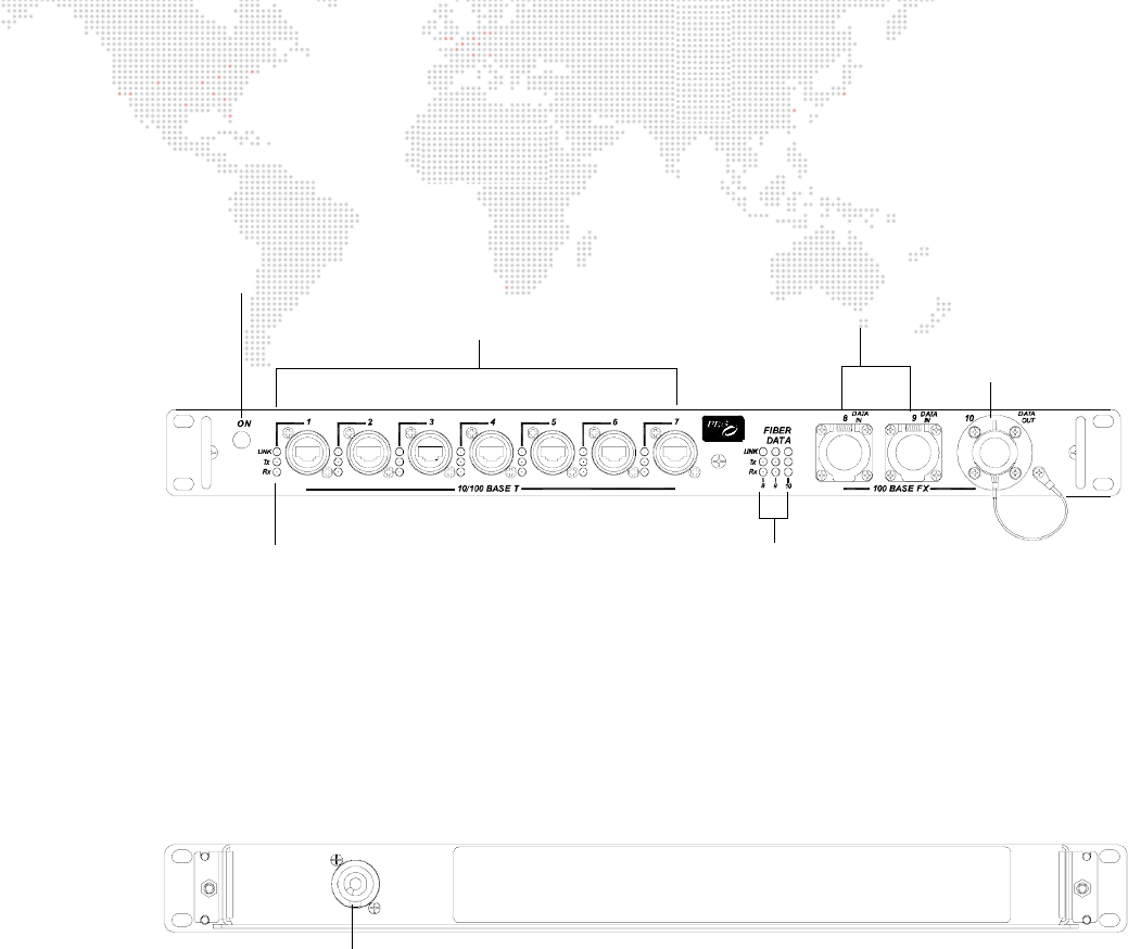
Controls and Indicators
The Series 400 10-Port Ethernet Switch contains the following connections and LED indicators.
Figure 2: 10-Port Ethernet Switch Front Panel
Figure 3: 10-Port Ethernet Switch Rear Panel
DC Power Indicator -
indicates AC power is applied.
Ethernet LEDs -
indicates valid Ethernet
link, transmit and receive
for each connection when lit.
10/100 Base T Connections -
input/output ports for standard signals.
Fiber Data LEDs -
indicates valid Fiber
link, transmit and receive
for each connection when lit.
Fiber Optic Input -
ports for fiber optic
cables with input
Fiber Optic Output -
port for a fiber optic
cable with an output
connector.
connectors.
Neutrik Connector -
Allows connection of AC Line Cord 208V PowerCon Cable (supplied).