WWW.PRG.
AutoPar®, Bad Boy®, PRG Series 400®, Mbox Extreme®, V676®, Virtuoso®, Virtuoso® DX, Virtuoso® DX2, and VL6C+™ are trademarks of Production Resource Group, LLC, registered in the U.S. and other countries. VARI❋LITE is a trademark owned by Genlyte Thomas Group LLC and is registered in the United States and other countries. All other brand names which may be mentioned in this manual are trademarks or registered trademarks of their respective companies.
FOREWORD Compliance Notice This device complies with Part 15 of the FCC rules. Operation is subject to the following two conditions: 1) This device may not cause harmful interference, and 2) This device must accept any interference received, including interference that may cause undesired operation.
WARNING: INSTRUCTIONS FOR PROTECTION AGAINST INJURY TO PERSONS 1) Exterior surfaces of the luminaire will be hot during operation. Use appropriate safety equipment (gloves, eye protection, etc.) when handling and adjusting hot equipment and components. Service and maintenance should be performed only by qualified personnel as determined by the high pressure lighting fixture manufacturer. 2) Arc lamps generate intense heat. Disconnect power and allow lamp to cool for 15 minutes before relamping.
Notes de sécurité Avant de procéder à l’installation des produits décrits dans ce guide et de les mettre en marche, il est extrêmement important de lire TOUS les renseignements et TOUTES les directives de sécurité contenues dans ce guide ainsi que toute documentation jointe. Tenir compte de tous les avertissements et suivre toutes les précautions pendant l’installation et l’utilisation de cet appareil.
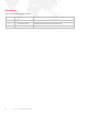
Revision History This manual has been revised as follows: IV Version Release Date Notes BASIC June 8, 2007 Initial release. A November 2, 2007 Changed product name from VL6C Plus to VL6C+. A1 November 3, 2010 Updated book format. (No change to technical information.
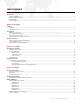
TABLE OF CONTENTS Introduction About This Manual........................................................................................................................................................................ Additional Documentation ............................................................................................................................................................ Special Note ....................................................................................................
Chapter 4. Troubleshooting and Maintenance Troubleshooting Basic Troubleshooting Guide...................................................................................................................................................... 42 Equipment Handling Proper Lamp Servicing and Operation ....................................................................................................................................... 43 Routine Maintenance Replacing the Lamp........................................
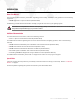
INTRODUCTION About This Manual This manual provides necessary information regarding product safety, installation, and operation for the following equipment: + VARI❋LITE VL6C+™ Spot Luminaire (20.9674.0002) Familiarizing yourself with this information will help you get the most out of your lighting system. WARNING: It is important to read ALL accompanying safety and installation instructions to avoid damage to the product and potential injury to yourself or others.
Customer Service Our comprehensive technical services department ensures you get the full benefit of being a PRG customer. Whether your needs are simple or complex, our full-time staff of experienced professionals are on-hand to provide support. For assistance, contact your nearest PRG office: PRG Dallas (International Service) 8617 Ambassador Row, Suite 120 Dallas, Texas 75247 Ph: 214.630.1963 Fx: 214.630.5867 Service Fx: 214.638.2125 Service Email: orders@prg.com PRG Atlanta 1053 Willingham Dr.
1. DESCRIPTION This chapter contains descriptions of luminaire features, components, and operations.
FEATURES Overview The VL6C+ Spot Luminaire from PRG Lighting is an improved version of the VARI❋LITE VL6C Spot Luminaire. Upgrades to the ventilation and airflow system provide superior reliability for all circuit boards and motors, while upgraded wiring and connectors further enhance the dependability and consistency of all motors and pan/tilt mechanisms.
Upgrade Summary The VL6C+ Spot Luminaire features many improvements over the standard VL6C Luminaire, both to the exterior and interior components. The following is a complete summary of improvements found in the VL6C+™ Spot Luminaire: + Reduced luminaire head temperatures to improve reliability of the optical mechanisms by increasing air flow through the head assembly.
COMPONENTS Exterior Components The following illustration shows the exterior VL6C+ components and controls.
Interior Head Components The following illustration shows the major sub-assemblies located in the VL6C+ Head.
The luminaire’s fixed color and gobo wheels have twelve (12) positions, while the rotating gobo wheel has six (6) positions. You can mix color filters and gobos on the same wheel, or have all filters on one wheel with all gobos on the other wheel. VL6C+ Spot Luminaires are shipped in a standard configuration with all gobos on the front wheel (Wheel 1) and all color filters on the rear wheel (Wheel 2). Color and gobo wheels can be placed on any step position of the motor.
Interior Yoke Components The following illustration shows the major sub-assemblies located in the VL6C+ Yoke. Pan Mechanism Ignitor PCB Main Controller PCB Relay Reset Switch Tilt Mechanism Aux Controller PCB Pan Mechanism TILT-SIDE YOKE LEG BOARD-SIDE YOKE LEG YOKE TOP VIEW TILT-SIDE YOKE LEG To determine which yoke leg is which, without having to remove the covers: Position the luminaire so that you are facing the front with the removable top cover facing up.
Replacement Items and Accessories The following items can be ordered from PRG. (Please order by PRG part number.) PRG P/N 71.2528.0700.0 Accessory MSR 700W Lamp 22.9634.0145 Series 300 Safety Cable 22.9634.0161 Series 300 Floor Stand 22.9634.0195 Series 300 Third-Point Truss Hook 22.9634.0217 Series 300 Double Truss Hook 25.7042.0006 6 ft. Shielded Series 300 Lamp Cable 25.7042.0012 12 ft. Shielded Series 300 Lamp Cable 25.7042.0020 20 ft. Shielded Series 300 Lamp Cable 25.7155.0050 50 ft.
OPERATION OVERVIEW External Power and Data Configuration Control data signals, 24Vdc, and lamp power are provided by a Series 300 Smart Repeater or Smart Repeater Plus processing unit to Series 300 luminaires via lamp cables. A maximum of three (3) VL6C+ Luminaires may be powered from a Smart Repeater unit and a maximum of six (6) VL6C+ Luminaires from a Smart Repeater Plus unit. Lamp power for VL6C+ Luminaires is provided by APS6 power supply modules located in a Series 300 Modular Rack.
Smart Repeater Units The Smart Repeater processing units combine electrical power and data signals from different sources and provide it for up to six VL6C+ Spot Luminaires via a single connector to each luminaire. Smart Repeater features: + Receives Virtuoso® or Series 200 data signal, and AC power for electronics through standard, 9-pin Series 200 lamp cable from ACS rack and sends it to connected luminaires.
Output connector providing power and signal to individual luminaire via luminaire lamp cable Circuit breaker protection for each output connector 10A Neon lamp power indicator for each output 10A 10A FRONT VIEW 10A 10A 10A Red Transmit LED indicates valid data between Repeater and luminaires Trunk Cable Connector (Socapex) receives lamp power from dimmers and Mod Racks, and S300 Trunk Cable Series 200 Lamp Cable Data Input Red and Green Broadcast LEDs indicate valid Virtuoso comm between Repeat
Internal Power and Data Distribution The following diagram shows how data and power are distributed within the VL6C+ Spot Luminaire.
2. INSTALLATION This chapter contains instructions for hanging or floor mounting the luminaire and connecting it to the system.
MOUNTING THE LUMINAIRE Attaching a Truss Hook The VL6C+ Spot Luminaire can be hung horizontally or vertically from any structure designed to accommodate the load created by this moving luminaire. In standard hanging applications, the VL6C+ Luminaire utilizes a Series 300 double truss hook, which is bolted to the pan tube. The hook can be oriented in 45 degree increments to provide flexible mounting. (See "Standard Hang" on page 17.
Hanging Methods Standard Hang In standard hanging applications, the VL6C+ Spot Luminaire utilizes a Series 300 double truss hook, which is bolted to the pan tube and affixed to square tube or round pipe; the minimum outside dimension for a piece of pipe or tube is 1 inch (2.54 cm) and the maximum outside dimension is 2 inches (5.08 cm). CAUTION: Wing bolts should be tightened only by hand. Do not use wrenches or other tools as this can damage the truss or the hook.
A Safety Cable MUST be used for all hanging installations and may be required by local codes. Safety cable and input pigtail cable must be dressed to avoid interference with luminaire motion. Square tube or round pipe. Minimum outside dimension for pipe or tube is 1 inch (2.54 cm). Maximum outside dimension is 2 inches (5.
Three-Point Hang A Series 300 third-point truss hook can be used to stabilize the luminaire in a three-point hanging configuration. The third-point hook is bolted to the pan tube in addition to the standard double hook. The following illustration shows how the hook is used to achieve a three-point hang. Series 300 Double Hook S300 Third-Point Truss Hook (22.9634.0195) Third-Point Hook Figure 2-3: Three-Point Hang Custom Hang The luminaire can also be hung using custom hanging devices.
Floor Mounting The VL6C+ Spot Luminaire may be mounted in an upright floor position using a Series 300 floor stand. The floor stand (22.9634.0161) includes all necessary hardware as shown in Figure 2-5. To install floor stand: Step 1. Orient pigtail cable as shown in Figure 2-5 DETAIL B and rotate pan tube accordingly. Step 2.
16.87" (428 mm) 8.43" (214 mm) 19.0" (482 mm) C L 19.0" (482 mm) 20.71" (526 mm) 25.13" (638 mm) 23.40" (594 mm) 0.53" (13 mm) 5.40" (137 mm) C L 9.72" (247 mm) 1.
SYSTEM CONNECTION Connecting to System (Typical) The VL6C+ Spot Luminaire requires a Smart Repeater unit for power and control by DMX512 consoles. (Refer to "Smart Repeater Units" on page 12 of the Operation Overview section.) Lamp power is provided by an APS6 power supply module installed in a Series 300 Modular Rack. WARNING: Voltages high enough to injure or kill a person exists in the AC power rack when power is applied.
There are five connections for a wye source and four connections for a delta source. Cables are often color coded to represent corresponding connections. Table 2-1: Delta/Wye Connections Delta Power * Wye Power Connection US Color Code UK Colour Code US Color Code UK Colour Code Phase X Black Gray Black Gray Phase Y Red Black Red Black Phase Z Blue Brown Blue Brown Neutral N/A N/A White Blue Ground Green Green Green Green * Not applicable in Europe.
Configuring Modular Rack and APS6 Modules Set Modular Rack SixPack chassis delta/wye switch(es) to correct setting: Determine requirements for either delta or wye load. + While operation as a delta load is typical in the U.S., most European countries require the system to be configured as a wye load. For example, if the house service is a wye-connected source and the phase-to-neutral voltage is 220, the system must be configured as a wye load.
Connect Series 300 Modular Rack to power source: Three-phase power will need to be supplied to the system. The maximum recommended Modular Rack power requirement is 200 amps, using 2/0 feeder with 4/0 Cam-Lok connectors and a 200A line disconnect. A SixPack Chassis requires 30 amps, and uses Hubbell or Epic connectors on 8/5 multicore cable. Connector choice is dependent upon location. This cable will need to be run from a house disconnect through a 30A line disconnect to the racks.
Configure APS6 module(s): Lamp power for the VL6C+ Spot Luminaire is provided by an APS6 power supply module installed in a Series 300 Modular Rack. CAUTION: Do not change mode or power setting with power applied to module. Step 1. At face of APS6 module(s), set rotary power switch to the 700W position (Figure 2-10). Step 2. Set mode switch to PSET for manual operation. Step 3. Apply power to lamp by moving circuit breaker switch to the ON position.
3. OPERATION This chapter contains instructions for power-up, reset and lamp dousing, along with DMX512 mapping information required for controlling the luminaire.
POWER-UP PROCEDURES Powering Up the Luminaire When power is applied, the VL6C+ Spot Luminaire will begin a calibration sequence which moves its pan, tilt, and all other mechanisms. After calibration, the luminaire head will either stop at its "home" position (which positions the pan and tilt axis at mid-rotation) or move to its current DMX-defined position if DMX512 data is present. All other mechanisms will also move to their "home" or DMX-defined positions.
Soft Reset A "soft reset" can be accomplished using the reset switch located in the yoke leg. During a soft reset, the lamp will not be extinguished, eliminating the need to wait for the lamp to cool down before restriking. To perform a soft reset: Step 1. Remove board-side yoke leg cover (Figure 3-1). Reset Switch Yoke Leg Cover Figure 3-1: Accessing the Reset Switch Step 2. Press reset switch. Step 3. Allow luminaire to execute reset and calibration procedure. Step 4. Replace yoke leg cover.
Lamp Douse Switch The lamp douse switch should be used to douse the arc lamp before disconnecting the pigtail cable. This will prevent damage to the contacts in the CPC connector, which can be caused by drawing an arc during disconnect. To douse the lamp, press the lamp douse switch located at the yoke cross-member. Lamp Douse Switch Pigtail Cable CPC Connector Figure 3-2: Lamp Douse Switch Location Note: Refer to "Proper Lamp Servicing and Operation" on page 43 for correct lamp operating procedures.
SMART REPEATER MODES Setting Smart Repeater DMX512 Modes There are a total of ten (10) software modes available for use in the Smart Repeater or Smart Repeater Plus units, allowing optimized control of the lighting system. Modes 5-10 apply to the VL6C+ Spot Luminaire. Below are brief descriptions of the modes and how to access them. Note: It is possible to have multiple modes in a single system, but not on a single Smart Repeater unit. MODE 5: 16-Bit with Reset - To set Mode 5, set the thumbwheel to 905.
DMX512 MAPPING DMX512 Mapping by Mode The following charts provide DMX512 mapping, by Smart Repeater mode, for the VL6C+ Spot Luminaire.
DMX Mode 6 Table 3-2: DMX Mode 6 (16-bit Extended) Port Number DMX Channel VL6C+ Luminaire 1 Intensity 2 Hi Byte Pan 3 Lo Byte Pan 4 Hi Byte Tilt 5 Lo Byte Tilt 6 Wheel 1 7 Wheel 2 8 Beam Iris 9 Lens (Edge) 10 Strobe 11 Zoom 12 Rotating Wheel 13 Rotation/Index 14 Focus Time 15 Color Time 16 Beam Time 17 Reset 2 18-34 -- 3 35-51 -- 4 52-68 -- 5 69-85 -- 6 86-102 -- 1 VL6C+ ™ SPOT LUMINAIRE USER MANUAL 33
DMX Mode 7 Applies to Smart Repeater Plus Unit ONLY.
DMX Mode 8 Applies to Smart Repeater Plus Unit ONLY.
DMX Mode 9 Applies to Smart Repeater Plus Unit ONLY. Table 3-5: DMX512 Mode 9 (16-bit with Reset) Port Number DMX Chan.
DMX Mode 10 Applies to Smart Repeater Plus Unit ONLY. Table 3-6: DMX512 Mode 10 (16-bit Extended) Port Number DMX Chan.
DMX512 Mapping by Component The following charts provide DMX512 mapping for all VL6C+ Luminaire functions.
Table 3-7: DMX512 Values for Fixed Wheels (Continued) Wheel Step/Position DMX Value % Value 153-155 60 35 156-158 34 33 Wheel Step/Position DMX Value % Value 15 207-209 81 61 14 210-211 82 159-160 62 13 212-214 83 161-163 63 12 215-216 84 164-165 64 11 217-219 85 31 166-168 65 10 220-221 86 30 169-170 66 9 222-224 87 29 171-173 67 8 225-226 88 174-175 68 7 227-229 89 27 176-178 69 6 230-232 90 26 179-181 70 5 233-234 91 25 182-183 71 4
The channel assigned to the rotating wheel selects the required gobo as follows: DMX Values Percent Values 156-255 Action DMX Values Percent Values Action Open 53-76 25 Gobo 2 129-153 55 Gobo 5 27-52 15 Gobo 1 102-128 45 Gobo 4 0-26 5 Open 77-102 35 Gobo 3 Value Action 0-2 Open 3-5 Closed 6-7 Slow Random 8-10 Medium Random 11-12 Fast Random 13-255 Where 13 is greatest interval and 255 is least interval (fastest) strobe Timing Channels Timing channel control improves t
4. TROUBLESHOOTING AND MAINTENANCE This chapter provides a basic troubleshooting guide, along with procedures for extended care of the luminaire and lamp. + TROUBLESHOOTING + EQUIPMENT HANDLING + ROUTINE MAINTENANCE For more detailed troubleshooting and maintenance procedures, refer to the VL6C+ Spot Luminaire Service Manual (02.9803.0010).
TROUBLESHOOTING Basic Troubleshooting Guide The following is a basic troubleshooting guide to get the luminaire up and running. For more extensive troubleshooting and testing, refer to the VL6C+ Spot Luminaire Service Manual (02.9803.0010). Symptom No power to luminaire No lamp output Hot spot visible in beam or beam not optimized 42 Cause(s) Refer to... Input cable not connected to Smart Repeater unit. page 11 Power not applied to Smart Repeater unit. page 11 No intensity value.
EQUIPMENT HANDLING Proper Lamp Servicing and Operation Servicing + When handling a lamp, hold it by the ceramic base while wearing cotton gloves or finger cots. Do not touch the glass envelope (bulb). If you touch the glass with bare fingers, wipe off any fingerprints with alcohol. Heat + When lamps are lit, the interior of the luminaires becomes very hot. To aid in the airflow circulation within the luminaires, after dousing the lamps, wait ten minutes before removing power to the luminaires.
ROUTINE MAINTENANCE Replacing the Lamp Parts: 71.2528.0700.0 LAMP, MSR 700W Tools: Screwdriver, #2 Phillips Screwdriver, slotted WARNING: Remove power from luminaire before performing any maintenance procedures. CAUTION: Refer to "Proper Lamp Servicing and Operation" on page 43 before handling the lamp. To replace lamp: Step 1. At APS6 module, remove power from lamp and allow lamp to cool for at least 5 minutes. Step 2. Remove power from luminaire. Step 3.
Aligning the Lamp The design of the VL6C+ optical system is based on an optimally flat field. A flat field is one where there is no detectable hot spot. After a new lamp is installed, it will be necessary to align the lamp to optimize the beam. Knobs located at the luminaire’s backcap allow for adjustment. Tools: Screwdriver, #2 Phillips To align lamp: WARNING: Backcap and adjustment knobs will be HOT during lamp operation. Wear gloves and/or use tools to prevent burns. To align lamp: Step 1.
Replacing a Standard Gobo or Color Filter Parts: Standard Gobo or Color Filter, as required Tools: Screwdriver, #2 Phillips WARNING: Remove power from luminaire before performing any maintenance procedures. To remove and replace a standard gobo or color filter: Step 1. Remove power from luminaire. Step 2. At head assembly, turn two captive screws one-quarter turn and remove cover (it will remain attached by tether). (Figure 4-3.) Step 3.
CAUTION: Do not touch gobo or color filters with bare fingers. Wear cotton gloves or other covering while replacing. Step 5. Using fingers, grasp frame of gobo or color filter and pull out of wheel hub (Figure 4-4.) Gobo or Color Filter Carrier Slot Gobo or Color Wheel Hub Figure 4-4: Replacing a Standard Gobo or Color Filter Step 6. Noting proper orientation of carrier slot, insert new gobo or color filter into position and push fully into place. Step 7.
Replacing a Rotating Gobo Parts: Rotating Gobo, as required Tools: Screwdriver, #2 Phillips WARNING: Remove power from luminaire before performing any maintenance procedures. To remove and replace a rotating gobo: Step 1. Remove power from luminaire. Step 2. At head assembly, turn two captive screws one-quarter turn and remove cover (it will remain attached by tether). (Refer back to Figure 4-3.) Step 3. At rotating gobo wheel, spin wheel so that desired gobo is accessible.
Cleaning the Luminaire Tools: Clean, lint-free cloth (2) Window cleaner 99% + Isopropyl alcohol Vacuum cleaner with brush nozzle or compressed air To clean the outside of the luminaire: WARNING: Remove power from luminaire before performing any maintenance procedures. CAUTION: Use caution when handling lenses or reflector. Avoid scratching optical surfaces. Step 1. Remove power from luminaire. Step 2. Using vacuum cleaner with brush nozzle or compressed air, clean dust from external components.
Notes 50 VL6C+ ™ SPOT LUMINAIRE USER MANUAL
A.
VL6C+ Spot Luminaire Description SOURCE: 700 Watt Short Arc Metal Halide Lamp Color Temperature 5600°K CRI 80 OUTPUT: 15,500 lumens BALLAST. Lamp power is provided by an APS6 module in the Modular Power Distribution Rack at 90 to 264 VAC, 50/60 Hz. LOW VOLTAGE: Luminaires are powered through a Smart Repeater or Smart Repeater Plus processing unit.* REFLECTOR: Precision glass reflector with dichroic cold mirror coating. OPERATING TEMP: -20° to 120°F (-29° to 49°C) COOLING: Forced air.
Photometric Data VL6C+ Luminaire with 700W Short Arc Metal Halide Lamp ZOOM LENS POSITION CANDELA* (cd) BEAM ANGLE (degrees) BEAM DIAMETER FIELD ANGLE (degrees) FIELD DIAMETER (Tn)1 NFOV 297,000 15.0° .263 18.5° .326 MFOV 104,000 25.0° .443 30.5° .545 WFOV 50,000 34.5° .621 42.5° .777 1 Multiply (Tn)1 throw distance by Tn to determine coverage.
Notes 54 VL6C+ ™ SPOT LUMINAIRE USER MANUAL
B. GLOSSARY This glossary provides useful terms associated with operating VL6C+ Spot Luminaires.
Glossary of Terms Address A numerical "name" given to a device on a DMX512 line indicating which of 512 possible channels it will respond to. Align (lamp) The process of adjusting the lamp within the reflector to obtain the desired output quality of the beam. APS6 Module The lamp power supply (ballast) for arc lamps found in the VL6C+ Luminaire. APS6 Trunk Cable Multi-conductor cable used to provide six circuits of arc lamp power to VARI❋LITE Series 300 luminaires.
DMX Power Pack The DMX Power Pack (DPP) is a portable electronics chassis that provides lamp power and control to Series 300 luminaires. DMX512 Universe A group of up to 512 DMX channels. Consoles may have more than one universe, usually labeled in groups of 512. Douse To de-energize a luminaire lamp. (Douse is unrelated to intensity states.) Epic Connector A six-pin, three-phase 35 amp connector found on 8/5 wire used to provide power to a Modular Rack SixPack chassis.
Intensity A value placed on the relative brightness of a lighting fixture; 100% is considered "full," and 0% is considered "out." Lamp Light source consisting of filament or electrodes, base, and envelope or "bulb." Lamp Cable VARI❋LITE cable that extends the fixture pigtail to a Smart Repeater unit. Luminaire Calibration The process of a luminaire finding its end stops for all parameters. Mini-Stepping Allows for smoother movement of color and gobo wheels in a VL6 spot luminaire.
SixPack Chassis Case used for lamp power distribution. Each chassis can contain up to six modules - APS6 and/or C3 in any combination. Each slot in the chassis corresponds to an output port on the Smart Repeater unit. The SixPack Chassis connects to the Smart Repeater unit through an APS Cable or standard Socapex cable (if no APS6 modules are used). Show File A file containing all programmed cue data. Shutter A mechanism which controls the douser or strobe action of luminaires capable of this function.
Tilt The movement of the luminaire around the axis of the tilt tube. Time Control of the duration of the change of the variable parameters of VARI❋LITE automated luminaires and other devices in a lighting system. Timing Channel A Timing Channel is used in lieu of cue fade rate to determine the time it will take a luminaire to move from one setting to another.
VL6C+™ Spot Luminaire User Manual Version as of: November 3, 2010 PRG part number: 02.9803.
Production Resource Group Dallas Office 8617 Ambassador Row, Suite 120 Dallas, Texas 75247 www.prg.