Owner’s Manual The Ultimate In Style & Performance® Exeter, PA St. Catharines, ON 1-800-800-8586 www.pridemobility.
SAFETY GUIDELINES The symbols below are used throughout this owner's manual and on the PMV to identify warnings and important information. It is very important for you to read them and understand them completely. WARNING! Indicates a potentially hazardous condition/situation that can cause personal injury, equipment and/or property damage. (Black symbol on yellow triangle with black border). MANDATORY! These actions should be performed as specified.
CONTENTS I. INTRODUCTION ......................................................................................................................... 4 II. SAFETY ......................................................................................................................................... 5 III. EMI/RFI ........................................................................................................................................ 16 IV. SPECIFICATIONS ...................................
I. INTRODUCTION SAFETY WELCOME to Pride Mobility Products Corporation (Pride). The product you have purchased combines state of the art components with safety, comfort and styling in mind. We are confident the design features will provide you with the conveniences you expect during your daily activities. Understanding how to safely operate and care for this product should bring you years of trouble free operations and service.
II. SAFETY PRODUCT SAFETY SYMBOLS The symbols below are used on the PMV to identify warnings, mandatory actions, and prohibited actions. It is very important for you to read and understand them completely. Pinch/Crush points created during assembly. Corrosive chemicals contained in battery. Use only AGM or Gel-Cell batteries to reduce the risk of leakage or explosive conditions. Read and follow the information in the owner’s manual. Maximum seating weight. Unlocked and in freewheel mode.
II. SAFETY Contact with tools can cause electrical shock. Front-to-rear plug orientation. Do not raise or lower the power seat while the PMV is in motion. Do not remove anti-tip wheels. Do not use a cell phone, walkie/talkie, laptop, or other radio transmitter while operating. Avoid exposure to rain, snow, ice, salt, or standing water whenever possible. Maintain and store in a clean and dry condition. Removal of grounding prong can create electrical hazard.
II. SAFETY GENERAL MANDATORY! Do not operate your new PMV for the first time without completely reading and understanding this owner’s manual. Your PMV is a state-of-the-art life-enhancement device designed to increase mobility. Pride provides an extensive variety of products to best fit the individual needs of the PMV user.
II. SAFETY PRE-RIDE SAFETY CHECK Get to know the feel of your PMV and its capabilities. Pride recommends that you perform a safety check before each use to make sure your PMV operates smoothly and safely. For details on how to perform these necessary inspections, see XI. “Care and Maintenance.” Perform the following inspections prior to using your PMV: ! Check for proper tire inflation (if equipped with pneumatic tires). ! Check all electrical connections. Make sure they are tight and not corroded.
II. SAFETY When climbing an incline, try to keep your PMV moving. If you must stop, start up again slowly, and then accelerate cautiously. When driving down an incline, do so by setting the speed adjustment dial to the slowest setting and driving in the forward direction only. If your PMV starts to move down the incline faster than you anticipated or desired, allow it to come to a complete stop by releasing the throttle control lever.
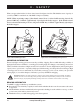
II. SAFETY When you approach an incline, it is best to lean forward. See figures 2 and 2A. This shifts the center of gravity of you and your PMV toward the front of the PMV for improved stability. NOTE: When negotiating ramps, if the throttle control lever is released while moving forward, the powered PMV may "rollback" approximately 1 foot before the brake engages.
II. SAFETY OUTDOOR DRIVING SURFACES Your PMV is designed to provide optimum stability under normal driving conditions—dry, level surfaces composed of concrete, blacktop, or asphalt. However, Pride recognises that there will be times when you will encounter other surface types. For this reason, your PMV is designed to perform admirably on packed soil, grass, and gravel. Feel free to use your PMV safely on lawns and in park areas.
II. SAFETY INCLEMENT WEATHER PRECAUTIONS Exposure of your PMV to inclement weather conditions should be avoided whenever possible. If suddenly caught up in rain, snow, severe cold or heat while operating your PMV proceed to shelter at the earliest oppurtunity. Thoroughly dry your PMV before storing, charging, or operating your PMV. WARNING! Operating in rain, snow, salt, mist/spray conditions, and on icy/slippery surfaces can cause personal injury and/or damage to the PMV and electrical system.
II. SAFETY ELEVATORS Modern elevators have a door edge safety mechanism that, when pushed, reopens the door(s). ! If you are in the doorway of a elevator when the door(s) begin to close, push on the rubber door edge or allow the rubber door edge to contact the PMV and the door will reopen. ! Use care that pocketbooks, packages, or PMV accessories do not become caught in elevator doors. NOTE: If your PMV’s turning radius is greater than 60 in.
II. SAFETY MOTOR VEHICLE TRANSPORT Currently, there are no standards approved for tie-down systems in a moving vehicle of any type to transport a person while seated in a PMV. Although your PMV may be equipped with a positioning belt, this belt is not designed to provide proper restraint during motor vehicle transport. Anyone traveling in a motor vehicle should be properly secured in the motor vehicle seat with safety belts fastened securely.
II. SAFETY POSITIONING BELTS Your authorized Pride Provider, therapist(s), and other healthcare professionals are responsible for determining your requirement for a positioning belt in order to operate your PMV safely. WARNING! If you require a positioning belt to safely operate your PMV, make sure it is fastened securely. Serious personal injury may result if you fall from the PMV. PRESCRIPTION DRUGS/PHYSICAL LIMITATIONS The PMV user must exercise care and common sense when operating his/her PMV.
III. EMI/RFI Electromagnetic and Radio Frequency Interference (EMI/RFI) Laboratory tests have shown that electromagnetic and radio frequency waves can have an adverse affect on the performance of electrically-powered mobility vehicles.
I V. S P E C I F I C AT I O N S 20.5" 46.5"- 51" 16.5" - 19.5" 4" REV ERS FO E 18" RW AR D 52" 18" 24" 19" 65" TURNING RADIUS 24" Figure 4. Hurricane Dimensions 4" 13" Figure 4A. Hurricane Tire Dimensions (Front and Rear) Hurricane www.pridemobility.
I V. Model Number Colors Overall Length Overall Width Total Weight Total Weight Without Batteries Heaviest Piece When Disassembled Turning Radius Speed (Maximum) Range Per Charge* Ground Clearance Weight Capacity Standard Seating Drive System Dual Braking System Tires Battery Requirements Battery Charger S P E C I F I C AT I O N S PMV5001 Candy Apple Red, Viper Blue, Champagne 52 in. 24 in. 285 lbs. 209 lbs. Rear section: 82 lbs. 65 in. 9 mph (With NF-22 batteries) Up to 30 miles 4 in. 400 lbs.
V. Y O U R PMV TILLER CONSOLE The tiller console houses all of the controls needed to drive your PMV, including the speed adjustment dial, half/full speed switch, throttle control lever, battery condition meter, lights switch, hazard lights switch, turn signal buttons, status LED, and horn buttons. See figure 5. WARNING! Do not expose the tiller console to moisture.
V. Y O U R PMV Key Switch ! Insert the key into the key switch and turn it clockwise to power up (turn on) your PMV. ! Turn the key counterclockwise to power down (turn off) your PMV. WARNING! If the key is moved to the “off” position while your PMV is in motion, the electronic brakes engage and your PMV will come to an abrupt stop! Lights Switch This switch controls your PMV’s lights. ! Toggle the switch forward to turn on your PMV’s rear running lights and front (upper) light.
V. Y O U R PMV Status LED The status LED alerts you to electrical problems that may occur with the PMV. The LED remains constantly lit while your PMV is on. If your PMV develops an electrical problem, the status LED will flash a code. See X. “Basic Troubleshooting” for flash codes. Tiller Console Fuses These fuses help protect your PMV’s front lighting, turn signals, and key switch console systems from receiving an overload of electrical current.
V. Y O U R PMV Motor/Transaxle Assembly (Not Shown) The motor/transaxle assembly is an electromechanical unit that converts electrical energy from your PMV’s batteries into the controlled mechanical energy that drives the PMV’s wheels. Manual Freewheel Lever Whenever you need or want to push your PMV for short distances, you can put it in freewheel mode. ! Remove the key from the key switch. ! Push forward on the manual freewheel lever to disable the drive system and the brake system.
VI . B AT T E R I E S A N D C H A R G I N G Your PMV requires two long-lasting, 12-volt, deep-cycle batteries that are sealed and maintenance free. They are recharged by an off-board charging system. ! Charge your PMV’s batteries prior to using it for the first time. ! Keep the batteries fully charged to keep your PMV running smoothly. READING YOUR BATTERY VOLTAGE The battery condition meter on the tiller console indicates the approximate strength of your batteries using a color code. See figure 7.
VI . B AT T E R I E S A N D C H A R G I N G 3. Make certain that the manual freewheel lever is in the drive position. 4. Plug the 3-pin charger power cord into the off-board charger port. See figures 9 and 10. 5. Extend the charger power cord and plug it into the wall outlet. 6. Turn the charger on. See figure 8. 7. When the batteries are fully charged, turn the charger off and unplug the charger power cord from the wall outlet and then from the off-board charger port.
VI . B AT T E R I E S A N D C H A R G I N G What if my PMV’s batteries won’t charge? ! Ensure the red (+) and black (-) battery cables are connected properly to the battery terminals. ! Ensure both battery harnesses that extend from the batteries are plugged into their mating harness leading to the charger. ! Ensure both ends of the charger power cord are inserted fully.
VI . B AT T E R I E S A N D C H A R G I N G What type and size of battery should I use? We recommend deep-cycle batteries that are sealed and maintenance free. Both AGM and Gel Cell are deep-cycle batteries that are similar in performance. Do not use wet-cell batteries, which have removable caps. WARNING! Corrosive chemicals are contained in batteries. Use only AGM or Gel-Cell batteries to reduce the risk of leakage or explosive conditions. NOTE: Sealed batteries are not serviceable.
VI . B AT T E R I E S A N D C H A R G I N G More importantly, it takes a few charging cycles (partial draining followed by full recharging) to establish the critical chemical balance that is essential to a deep-cycle battery’s peak performance and long life. Follow these steps to properly break in your PMV’s new batteries for maximum efficiency and service life. 1. Fully recharge any new battery prior to its initial use. This charging cycle brings the battery up to about 88% of its peak performance level.
VII. O P E R AT I O N BEFORE GETTING ON YOUR PMV ! Have you fully charged the batteries? See VI. “Batteries and Charging.” ! Is the manual freewheel lever in the drive (backward) position? Never leave the manual freewheel lever pushed forward unless you are manually pushing your PMV. GETTING ONTO YOUR PMV WARNING! Never attempt to get onto or off of your PMV without first removing the key from the key switch. This will prevent the PMV from moving if accidental throttle control lever contact is made. 1.
VII. ! ! ! ! O P E R AT I O N Pull on the left handgrip to steer your PMV to the left. Pull on the right handgrip to steer your PMV to the right. Move the tiller to the center position to drive straight ahead. To stop, slowly release the throttle control lever. After you release the throttle control lever, gently squeeze the handbrake (if equipped) to come to a complete stop. The electronic brakes will automatically engage when your PMV comes to a stop.
VIII. COMFORT ADJUSTMENTS WARNING! Remove the key from the key switch before adjusting the tiller or the seat. Never attempt to adjust the tiller or the seat while the PMV is in motion. TILLER ANGLE ADJUSTMENT Your PMV is equipped with a pivoting tiller that allows adjustment to several positions from the PMV deck to the farthest forward stop. 1. Lift the tiller adjustment lever. See figure 11. 2. Move the tiller to a comfortable position. 3.
VIII. COMFORT ADJUSTMENTS ARMREST ANGLE ADJUSTMENT The armrest angle of your PMV can be adjusted upward or downward by turning the adjustment dial. See figure 12B. ADJUSTMENT DIAL NOTE: Pivot the armrests upward to make getting onto and off of your PMV easier. SEAT HEIGHT ADJUSTMENT You can change the seat height to one of three positions in 1-in. increments. See figure 13. Changing the seat height: 1. Remove the seat and shroud from your PMV. See IX. “Disassembly and Assembly.” 2.
VIII. COMFORT ADJUSTMENTS POWER SEAT (OPTIONAL) Your PMV may be equipped with a power seat. The power seat actuator is designed to raise or lower the seat automatically with minimal effort on the part of the operator. The power seat switch is located on the tiller console. Operating your power seat: 1. Release the throttle control lever. 2. Ensure your PMV is level and stationary. 3. Set the speed adjustment dial to the slowest setting 4.
IX. D I S A S S E M B LY AND A S S E M B LY DISASSEMBLY You can disassemble the PMV into seven pieces: the seat, the front section, the rear section, the rear shroud, the basket, and the batteries. See figure 14. No tools are required to disassemble or assemble your PMV. Since the disassembled sections of the PMV take up more floor space than the assembled unit, place the PMV on a level, dry surface with sufficient room to move the parts around. You will need about five feet in all directions.
182 Susquehanna Ave. Exeter, PA 18643 1-800-800-8586 www.pridemobility.
IX. D I S A S S E M B LY Toggle Latch Release 1. Push in the toggle latch release button while pulling back the toggle latch. See figures 16 and 16A. 2. Position the toggle latch buckle over the top of the toggle latch. See figure 16B. Frame Separation 1. Lower the tiller to the PMV floorboard. 2. Push back on the seat post to pivot the PMV’s rear section rearwards until the rear section is standing vertically on its bumper. See figure 17. 3.
X. BASIC TROUBLESHOOTING Any electromechanical device occasionally requires some troubleshooting. However, most of the problems that may arise can usually be solved with a bit of thought and common sense. Many of these problems occur because the batteries are not fully charged or because the batteries are worn down and can no longer hold a charge. DIAGNOSTIC FLASH CODES The diagnostic flash codes for your PMV are designed to help you perform basic troubleshooting quickly and easily.
X. BASIC TROUBLESHOOTING What if the main circuit breaker repeatedly trips? ! Charge the PMV’s batteries more frequently. See VI. “Batteries and Charging.” ! If the problem continues, have both of your PMV’s batteries load tested by your authorized Pride Provider. ! You may also perform the load test yourself. Battery load testers are available at most automotive parts stores. ! Follow the directions supplied with the load tester. ! See IV. “Specifications” for information about your PMV’s battery type.
XI. CARE AND MAINTENANCE Your PMV requires a minimal amount of care and maintenance. If you do not feel confident in your ability to perform the maintenance listed below, you may schedule inspection and maintenance at your authorized Pride Provider. The following areas require periodic inspection and/or care and maintenance. TIRE PRESSURE ! If equipped with pneumatic tires, always maintain a proper 30-35 psi tire pressure.
XI. CARE AND MAINTENANCE CONSOLE, CHARGER, AND REAR ELECTRONICS ! Keep these areas free of moisture. ! Allow these areas to dry thoroughly if they have been exposed to moisture before operating your PMV again. FUSE REPLACEMENT In the event a fuse should cease to work: ! Remove the fuse by pulling it out of its slot. ! Examine the fuse to be sure it is blown. See figures 20 and 21. ! Insert a new fuse of the proper rating. Figure 20. Working Fuse Figure 21.
XII.
XII.
NOTES Hurricane www.pridemobility.
182 Susquehanna Ave. Exeter, PA 18643 1-800-800-8586 www.pridemobility.