JAZZY 600 SERIES How a Power Chair should FEEL!™ Including Models: Jazzy 600 2S, Jazzy 600 2SP, Jazzy 600 3S, Jazzy 600 3SP, Jazzy 600XL 1-800-800-8586 (US) 1-888-570-1113 (Canada)
SAFETY GUIDELINES The symbols below are used throughout this owner's manual and on the power chair to identify warnings and important information. It is very important for you to read them and understand them completely. WARNING! Indicates a potentially hazardous condition/situation. Failure to follow designated procedures can cause either personal injury, component damage, or malfunction. On the product, this icon is represented as a black symbol on a yellow triangle with a black border.
CONTENTS I. INTRODUCTION.................................................................................................................................... 4 II. SAFETY .................................................................................................................................................... 6 III. YOUR POWER CHAIR ....................................................................................................................... 16 IV. ASSEMBLY.............................
I. INTRODUCTION SAFETY WELCOME to Pride Mobility Products Corporation (Pride). The power chair you have purchased combines state-ofthe-art components with safety, comfort, and styling in mind. We are confident that these design features will provide you with the conveniences you expect during your daily activities. Once you understand how to safely operate and care for your power chair, it should give you years of trouble free operation and service.
I. INTRODUCTION PRIDE OWNERS CLUB As an owner of a Pride product, you are encouraged to enroll in the Pride Owners Club. Complete and return your enclosed product registration card or visit Pride’s web site at www.pridemobility.com. From our home page, select “Owners Club” to enter a page dedicated to current and potential Pride product owners. You will gain access to interviews, stories, recreation ideas, daily living tips, product and funding information, and interactive message boards.
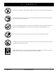
II. SAFETY PRODUCT SAFETY SYMBOLS The symbols below are used on the power chair to identify warnings, mandatory actions, and prohibited actions. It is very important for you to read and understand them completely. Corrosive chemicals contained in battery. Use only AGM or Gel-Cell batteries to reduce the risk of leakage or explosive conditions. This product has been tested and passed at an immunity level of 20 V/m. Read and follow the information in the owner’s manual. Maximum seating weight.
II. SAFETY Do not use a cell phone, walkie/talkie, laptop, or other radio transmitter while operating. Avoid exposure to rain, snow, ice, salt, or standing water whenever possible. Maintain and store in a clean and dry condition. Removal of grounding prong can create electrical hazard. If necessary, properly install an approved 3-pronged adapter to an electrical outlet having 2-pronged plug access. Do not connect an extension cord to the AC/DC converter or the battery charger.
II. SAFETY GENERAL GUIDELINES MANDATORY! Do not operate your new power chair for the first time without completely reading and understanding this owner’s manual. Your power chair is a state-of-the-art life-enhancement device designed to increase mobility. Pride provides an extensive variety of products to best fit the individual needs of the power chair user.
II. SAFETY Weight Limitations Your power chair is rated for a maximum weight capacity. Please refer to the specifications table for this limit. WARNING! Stay within the specified weight capacity of your power chair. Exceeding the weight capacity voids your warranty. Pride will not be held responsible for injuries and/or property damage resulting from failure to observe weight limitations. WARNING! Do not carry passengers on your power chair.
II. SAFETY WARNING! Even though your power chair is capable of climbing slopes greater than those illustrated in figure 1, do not, under any circumstances, exceed the incline guidelines or any other specifications presented in this manual. Doing so could cause instability in your power chair. In compliance with the Americans with Disabilities Act of 1990, all handicap public access ramps are required to have a maximum slope of 5° (8.7%).
II. SAFETY Public Streets and Roadways WARNING! You should not operate your power chair on public streets and roadways. Be aware that it may be difficult for traffic to see you when you are seated on your power chair. Obey all local pedestrian traffic rules. Wait until your path is clear of traffic, and then proceed with extreme caution.
II. SAFETY WARNING! Do not attempt to have your power chair climb or descend an obstacle that is higher than 2 in. (5 cm) unless you have the assistance of an attendant. WARNING! Do not attempt to have your power chair proceed backward down any step, curb, or other obstacle. This may cause the power chair to tip. Stairs and Escalators Power chairs are not designed to travel up or down stairs or escalators. Always use an elevator. WARNING! Never use your power chair to negotiate steps or escalators.
II. SAFETY Batteries In addition to following the warnings below, be sure to comply with all other battery handling information. For more information about your power chair’s batteries, see VI. “Batteries and Charging.” WARNING! Power chair batteries are heavy. See specifications table. If you are unable to lift that much weight, be sure to get help. Use proper lifting techniques and avoid lifting beyond your capacity.
II. SAFETY Transfers Transferring onto and off of your power chair requires a good sense of balance. Always have an attendant or healthcare professional present while learning to properly transfer yourself. To eliminate the possibility of injury, Pride recommends that you or a trained attendant perform the following tasks before attempting a transfer: ! Turn off the power to the controller. ! Ensure your power chair is not in freewheel mode. See III. “Your Power Chair.
II. SAFETY WARNING! Although the power chair seat has passed the necessary testing requirements for cigarette smoke, Pride recommends that you adhere to the following safety guidelines: ! Do not leave lit cigarettes unattended. ! Keep ashtrays a safe distance from the seat cushions. ! Always make sure cigarettes are completely extinguished before disposal.
III. YOUR POWER CHAIR THE JAZZY 600 SERIES Your power chair has two main assemblies: the seat assembly and the power base assembly. See figure 5. Typically, the seat assembly includes the armrests, seatback, and seat base. The power base assembly includes two motor/brake assemblies, two drive wheels, four caster wheels, two batteries, and wiring harnesses. See figures 5, 6, and 7.
III. YOUR POWER CHAIR SPECIFICATIONS Suspension: ATX Suspension (Active-Trac with extra stability) Drive Wheels: Jazzy 600 Series: 14 in. (35.56 cm), pneumatic or solid available Jazzy 600XL: 14 in. (35.56 cm), solid Front Caster Wheels: 5 in. (12.7 cm), solid Rear Caster Wheels: 6 in. (15.24 cm), solid Maximum Speed:¹ Jazzy 600 Series: Up to 5 mph (8.04 km/h) Jazzy 600XL: Up to 4 mph (6.
III. YOUR POWER REAR SHROUD FASTENERS CHAIR TRAPEZE BARS FRONT COVER MOTOR/BRAKE ASSEMBLY Figure 6. The Jazzy 600 Series Power Base ELECTRICAL COMPONENTS The electrical components are located inside the power base. The ammeter and the charger power cord receptacle are located on the right side of the power base. The main circuit breaker is located on the front of the battery tray. The controller connector(s) are located inside the power base. See figure 7.
III. YOUR POWER CHAIR Controller Connector: This is where the controller connects to the power module or power base. Each controller uses a different type of cable. Regardless of which type of controller is used, the cable must be secured to the seat assembly and not allowed to drag on the floor. Main Circuit Breaker: The main circuit breaker is a safety feature built into your power chair. When the batteries and the motors are heavily strained (e.g.
III. YOUR POWER CHAIR Manual Freewheel Levers Your power chair has a manual freewheel lever on each motor. Manual freewheel levers enable you to disengage the drive motors from the gearboxes and maneuver the chair manually. WARNING! Do not use the power chair while the drive motors are disengaged! Do not disengage the drive motors when the power chair is on an incline, as the unit could roll on its own! Only engage the freewheel mode when on a level surface.
I V. ASSEMBLY INITIAL ASSEMBLY Your power chair may require some assembly either before initial use or after transportation. It may also require disassembly to make some comfort adjustments. Figure 10 details those parts of the power chair that are designed to be disassembled and assembled by an end user or by a qualified caregiver before using the product or making comfort adjustments.
I V. ASSEMBLY Seat Installation It may be necessary to install the seat either prior to initial operation or after transporting your power chair. Most seats are attached to the power base with the Universal Mounting System (UMS). The UMS consists of universal parts that may be attached to any medium-back or high-back seat, regardless of seat width or seat depth. The two main components are aluminum extrusions mounted to the seat base.
V. COMFORT ADJUSTMENTS COMFORT ADJUSTMENTS After becoming familiar with your power chair’s operation, you may find the need to make some adjustments to increase your comfort, such as seat height and angle, armrest angle, foot platform height and angle, and controller position. NOTE: If your power chair is equipped with a Specialty Seat or TRU-Balance Power Positioning System, refer to the seat adjustment information contained in separate manuals.
V. COMFORT ADJUSTMENTS NOTE: Change the seat dump by raising or lowering only one set of towers (front or back). 10. Reinstall the retaining clips from step 8. 11. Remove each screw from the trapeze bars and apply thread lock. 12. Reinstall each screw into the trapeze bars and tighten. 13. Reinstall the seat. 14. Reconnect the controller to the power base. 15. Reinstall the rear shroud and tighten the rear shroud fasteners.
V. COMFORT Seatback Angle Adjustment If your power chair is equipped with an adjustable seatback, you can adjust it to four (4) different angles: 90°, 102°, 105°, or 107°. To adjust the seatback angle: 1. Remove the adjusting screws from each seat hinge. See figure 15. 2. Set the seatback at the desired angle. 3. Reinstall the adjusting screws to each seat hinge and tighten.
V. COMFORT ADJUSTMENTS Controller Position You can move the controller in toward or out away from the armrest, or change the position of the controller for either left-hand or right-hand use. WARNING! Do not place the controller cable so that it can be pinched in the seat frame or the power base frame. CONTROLLER BRACKET SETSCREW To extend the controller: 1. Flip up the armrest so it is perpendicular to the floor. 2. Loosen the setscrew on the controller bracket. See figure 16. 3.
V. COMFORT Foot Platform Depth Adjustment To adjust the foot platform depth: 1. Remove the quick release fasteners from the foot platform bracket. See figure 17. 2. Move the foot platform in or out to the desired depth. 3. Reinstall the quick release fasteners into the foot platform bracket and tighten. Quick Release Fasteners: The foot platform is attached to the power base with two quick release fasteners. See figure 17. Each quick release fastener consists of a bolt, a lever, and a nut. See figure 18.
V. COMFORT ADJUSTMENTS Swing-away Footrests Swing-away Footrests (SFRs) enable you to rotate the footrests to the side before you transfer onto or off or your power chair. See figure 20. SFR RELEASE LEVER FOOTREST EXTENSION To rotate the SFRs: 1. Push in the release lever. 2. Rotate the SFRs. To adjust the SFR length: 1. Remove the two adjustment screws from the side of each footrest extension. 2. Slide the footrest up or down to the desired length. 3. Reinstall the two adjustment screws.
V. COMFORT ADJUSTMENTS To adjust the leg rest length: 1. Remove the adjustment screws from the leg rest extension. 2. Slide the leg rest up or down to the desired length. 3. Align the adjustment holes in the leg rest extension and reinstall the adjustment screws. Multi-Axis Foot Plates The multi-axis foot plate assembly can be installed on either a swing-away footrest or an elevating leg rest. The multiaxis foot plate has four adjustments: leg rest length (A), position (B), tilt (C), and angle (D).
VI. BATTERIES AND CHARGING BATTERIES AND CHARGING Your power chair uses two long-lasting, 12-volt, deep-cycle batteries. These batteries are sealed and maintenance free. Since they are sealed, there is no need to check the electrolyte (fluid) level. Deep-cycle batteries are designed to handle a longer and deeper discharge. Though they are similar in appearance to automotive batteries, they are not interchangeable.
VI. BATTERIES AND CHARGING WARNING! If your battery charger has not been tested and approved for outdoor use, then do not expose it to adverse or extreme weather conditions. If the battery charger is exposed to adverse or extreme weather conditions, then it must be allowed to adjust to the difference in environmental conditions before use indoors. Refer to the manual supplied with the battery charger for more information. To charge the batteries using the optional onboard charger: 1.
VI. BATTERIES AND CHARGING Frequently Asked Questions (FAQs) How does the charger work? The battery charger takes the standard electrical outlet voltage of 120 VAC (alternating current) and converts it to 24 VDC (direct current). The power chair batteries use direct current to run your power chair. When the battery voltage is low, the charger works harder to charge the battery. As the battery voltage approaches full charge, the charger doesn’t work as hard to complete the charging cycle.
VI. BATTERIES AND CHARGING WARNING! Corrosive chemicals contained in batteries. Use only AGM or Gel-Cell batteries to reduce the risk of leakage or explosive conditions. Why do my new batteries seem weak? Deep-cycle batteries employ a much different chemical technology than that used in car batteries, nickel-cadmium (nicads), or in other common battery types. Deep-cycle batteries are specifically designed to provide power, drain down their charge, and then accept a relatively quick recharge.
VII. CARE AND MAINTENANCE CARE AND MAINTENANCE Your Jazzy 600 is a sophisticated power chair. Like any motorized vehicle, it requires routine maintenance checks. You can perform some of these checks, but others require assistance from your authorized Pride Provider. Preventive maintenance is very important. If you follow the maintenance checks in this section as scheduled, you can help ensure that your power chair gives you years of trouble-free operation.
VII. CARE AND MAINTENANCE ! All wheel bearings are prelubricated and sealed. They require no subsequent lubrication. ! The body shroud has been sprayed with a clear sealant coating. You can apply a light coat of car wax to help it retain its high-gloss appearance. ! Check all electrical connections. Make sure they are tight and are not corroded. Batteries must sit flat within the battery tray, with the battery terminals facing inward, toward each other.
VII. CARE AND MAINTENANCE Yearly Checks Take your power chair to your authorized Pride Provider for yearly maintenance, especially if you use your power chair on a daily basis. This helps ensure that your power chair is functioning properly and helps prevent future complications. Storage Your power chair should be stored in a dry place, free from temperature extremes. When storing, disconnect the batteries from the power chair. See VI. “Batteries and Charging.
VII. CARE AND MAINTENANCE TIRE AXLE KEY TUBE AXLE SLOT FRONT RIM HALF SCREWS REAR RIM HALF DRIVE WHEEL WASHER DRIVE WHEEL NUT Figure 24. Jazzy 600 Drive Wheel Figure 25. Jazzy 600 Drive Wheel Disassembled Follow these easy steps for a quick and safe repair for both pneumatic and solid tires: 1. Turn off the power to the controller. 2. Set the power chair up on blocks. 3. If you are changing a pneumatic tire, completely deflate it before removing the wheel. 4.
VII. CARE AND MAINTENANCE REAR SHROUD FASTENERS REAR SHROUD BATTERY WIRING DIAGRAM LABEL FRONT BATTERY REAR BATTERY Figure 26. Battery Installation 38 www.pridemobility.
VII. CARE AND MAINTENANCE To replace the batteries: 1. Turn off the power to the controller. 2. Make sure that the power chair is in drive mode. See III. “Your Power Chair.” 3. Turn the rear shroud fasteners one-quarter turn in any direction. See figure 26. 4. Remove the rear shroud. 5. Disconnect the battery harness from the rear battery. 6. Remove the retaining pin and lift off the front cover using the foot platform bracket. See figure 17. 7. Slide the battery tray forward. 8.
VIII.
VIII. WARRANTY RECONDITIONED UNITS WARRANTY All reconditioned units are covered by a six-month warranty from Pride effective from the date of purchase. WARRANTY EXCLUSIONS This warranty does not extend to those items which may require replacement due to normal wear and tear.
NOTES 42 www.pridemobility.
Quality Control - Jazzy 600 Series Inclusion of all Parts Joystick Serial Number Controller Serial Number Left Motor Serial Number Right Motor Serial Number Fit and Finish Performance Pride keeps a more detailed report on file at the factory.