Owner’s Manual Exeter, PA St. Catharines, ON 1-800-800-8586 www.pridemobility.
SAFETY GUIDELINES The symbols below are used throughout this owner's manual and on the power chair to identify warnings and important information. It is very important for you to read them and understand them completely. WARNING! Failure to follow designated procedures can cause either personal injury, component damage, or malfunction (black symbol on yellow triangle with black border). MANDATORY! These actions should be performed as specified.
CONTENTS I. INTRODUCTION................................................................................................................................. 4 II. SAFETY ................................................................................................................................................. 6 III. YOUR POWER CHAIR .................................................................................................................... 15 IV. ASSEMBLY......................................
I. INTRODUCTION SAFETY WELCOME to Pride Mobility Products Corporation (Pride). The power chair you have purchased combines state-ofthe-art components with safety, comfort, and styling in mind. We are confident that these design features will provide you with the conveniences you expect during your daily activities. Once you understand how to safely operate and care for your power chair, it should give you years of trouble free operation and service.
I. INTRODUCTION PRIDE OWNERS CLUB As an owner of a Pride product, you are invited to register your product’s warranty and enroll in the Pride Owners Club. You may do so by filling out and returning your enclosed product registration card or by visiting Pride's web site at www.pridemobility.com. As a registered member, each time you visit our site, you will have access to the most interactive and honest educational venue available today for people with mobility needs, their families, and friends.
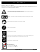
II. SAFETY PRODUCT SAFETY SYMBOLS The symbols below are used on the power chair to identify warnings, mandatory actions, and prohibited actions. It is very important for you to read and understand them completely. Corrosive chemicals contained in battery. Use only AGM or Gel-Cell batteries to reduce the risk of leakage or explosive conditions. EMI-RFI - This product has been tested and passed at an immunity level of 20 V/m. Read and follow the information in the owner’s manual. Maximum seating weight.
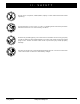
II. SAFETY Do not use a cell phone, walkie/talkie, laptop, or other radio transmitter while operating. Avoid exposure to rain, snow, ice, salt, or standing water whenever possible. Maintain and store in a clean and dry condition. Removal of grounding prong can create electrical hazard. If necessary, properly install an approved 3-pronged adapter to an electrical outlet having 2-pronged plug access. Failure to heed could result in personal injury and/or property damage.
II. SAFETY SAFETY MANDATORY! Do not operate your new power chair for the first time without completely reading and understanding this owner’s manual. Your power chair is a state-of-the-art life-enhancement device designed to increase mobility. Pride provides an extensive variety of products to best fit the individual needs of the power chair user.
II. SAFETY Weight Limitations Your power chair is rated for a maximum weight capacity. Please refer to the specifications table for this limit. WARNING! Exceeding the weight capacity voids your warranty and may result in personal injury and/or damage to your power chair. Pride will not be held responsible for injuries and/or property damage resulting from failure to observe weight limitations. WARNING! Do not carry passengers on your power chair.
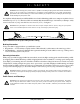
II. SAFETY WARNING! Even though your power chair is capable of climbing slopes greater than those illustrated in figure 1, do not, under any circumstances, exceed the incline guidelines or any other specifications presented in this manual. Doing so could cause instability in your power chair, resulting in personal injury and/or damage to your power chair. In compliance with the Americans with Disabilities Act of 1990, all handicap public access ramps are required to have a maximum slope of 5° (8.7%).
II. SAFETY Freewheel Mode Your power chair is equipped with two manual freewheel levers to allow for manual maneuverability by a trained attendant. For more information about how to place your power chair into and out of freewheel mode, see III. “Your Power Chair.” WARNING! Do not use your power chair in freewheel mode without an attendant present. Personal injury may result. WARNING! Do not attempt to personally place your power chair in freewheel mode while seated on it. Personal injury may result.
II. SAFETY Transfers Transferring onto and off of your power chair requires a good sense of balance. Always have an attendant or healthcare professional present while learning to properly transfer yourself. To eliminate the possibility of injury, Pride recommends that you or a trained attendant perform the following tasks before attempting a transfer: ! Turn the the power to the controller. See VII. “Operation.” ! Ensure your power chair is not in freewheel mode. See III. “Your Power Chair.
II. SAFETY Inclement Weather Precautions Exposure of your power chair to inclement weather conditions should be avoided whenever possible. If suddenly caught up in rain, snow, severe cold or heat while operating your power chair proceed to shelter at the earliest opportunity. Thoroughly dry your power chair before storing, charging, or operating your power chair.
II. SAFETY Removable Parts WARNING! Do not attempt to lift or move a power chair by any of its removable parts. Personal injury and/or damage to the power chair may result. Preventing Unintended Movement WARNING! If you anticipate being seated in a stationary position for an extended period of time, turn off the power. This will prevent unexpected motion from inadvertent joystick contact. This will also eliminate the possibility of unintended chair movement from electromagnetic (EM) sources.
III. YOUR POWER CHAIR THE JAZZY 600 XL The Jazzy 600 XL has two main assemblies: the seat assembly and the power base assembly. See figure 5. Typically, the seat assembly includes the armrests, seatback, and seat base. The power base assembly includes two motor/brake assemblies, two drive wheels, four caster wheels, two batteries, and wiring harnesses. See figures 5, 6, and 7.
III. YOUR POWER CHAIR JAZZY 600 XL S PECIFICA TIONS SPECIFICA PECIFICATIONS Suspension: Active-Trac Extreme Drive Wheels: 14 in., solid Front Caster Wheels: 5 in., solid Rear Caster Wheels: 6 in., solid Maximum Speed: Up to 4 mph* Brakes: “Intelligent Braking” electronic regenerative, disc park brake Ground Clearance: 3.0 in. Turning Radius: 20 in. (without foot riggings) Overall Size: Length: 37.5 in. (without foot riggings) Length: 41.5 in. (with foot platform) Width: 23 in.
III. YOUR POWER CHAIR REAR SHROUD FASTENERS TRAPEZE BARS FRONT COVER MOTOR/BRAKE ASSEMBLY Figure 6. The Jazzy 600 XL Power Base ELECTRICAL COMPONENTS The electrical components are located inside the power base. The ammeter and the charger power cord receptacle are located on the right side of the power base. The main circuit breaker is located on the front of the battery tray. The controller connector(s) are located inside the power base. See figure 7.
III. YOUR POWER CHAIR Battery Connector: This is where the controller connects to the batteries. Controller Connector (FLIGHT Only): This is where the controller connects to the power module. Main Circuit Breaker: The main circuit breaker is a safety feature built into your power chair. When the batteries and the motors are heavily strained (e.g., from excessive loads), the main circuit breaker trips to prevent damage to the motors and the electronics.
III. YOUR POWER CHAIR MANUAL FREEWHEEL LEVERS The Jazzy 600 XL has a manual freewheel lever on each motor. Manual freewheel levers enable you to disengage the drive motors from the gearboxes and maneuver the chair manually. WARNING! Do not use the power chair while the drive motors are disengaged! Do not disengage the drive motors when the power chair is on an incline, as the unit could roll on its own, causing injury! To engage or disengage the drive motors: 1. Locate the lever on top of each motor.
I V. ASSEMBLY INITIAL ASSEMBLY Your power chair may require some assembly either before initial use or after transportation. It may also require disassembly to make some comfort adjustments. Figure 10 details those parts of the power chair that are designed to be disassembled and assembled by an end user or by a qualified caregiver before using the product or making comfort adjustments.
I V. ASSEMBLY SEAT INSTALLATION It may be necessary to install the seat either prior to initial operation or after transporting your power chair. Most seats are attached to the power base with the Universal Mounting System (UMS). The UMS consists of universal parts that may be attached to any medium-back or high-back seat, regardless of seat width or seat depth. The two main components are aluminum extrusions mounted to the seat base.
V. COMFORT ADJUSTMENTS COMFORT ADJUSTMENTS After becoming familiar with your power chair’s operation, you may find the need to make some adjustments to increase your comfort, such as seat height and angle, armrest angle, foot platform height and angle, and controller position. If your power chair is equipped with a medium-back, a high-back, or a reclining seat, refer to the following information.
V. COMFORT ADJUSTMENTS 12. Reinstall each screw into the trapeze bars and tighten. 13. Reinstall the seat. 14. Reconnect the controller to the power base. 15. Reinstall the rear shroud and tighten the rear shroud fasteners. Seat Position You can move the seat forward or rearward by changing the extrusion mounting position. To change the position: 1. Turn off the power to the controller. 2. Loosen the rear shroud fasteners and remove the rear shroud. 3.
V. COMFORT ADJUSTMENTS Armrest Width Adjustment You can change each armrest’s width independently of the other. FOOT PLATFORM RETAINING PIN NOTE: Changing the armrest width may increase the overall width of your power chair. To change the armrest width: 1. Locate the two armrest knobs on each side of the armrest receiver bracket. See figure 16. 2. Loosen the knobs. 3. Slide the armrests in or out to the desired width. 4. Tighten the knobs.
V. COMFORT two states: clamped and unclamped. When the lever is open, the quick release fastener is unclamped. When the lever is closed, the quick release fastener is clamped. ADJUSTMENTS SETSCREW To clamp the quick release fastener: 1. Make sure the lever is in the open position. 2. Turn the nut clockwise until it is snug. 3. Rotate the lever until it is in the fully closed position.
V. COMFORT ADJUSTMENTS Swing-away Footrests Swing-away Footrests (SFRs) enable you to rotate the footrests to the side before you transfer onto or off or your power chair. See figure 20. ADJUSTMENT BOLT To rotate the SFRs: 1. Push in the release lever. 2. Rotate the SFRs. LEG REST HANGER ADJUSTMENT SCREWS LEG REST EXTENSION To adjust the SFR length: 1. Remove the two adjustment screws from the side of each footrest extension. 2. Slide the footrest up or down to the desired length. 3.
V. COMFORT ADJUSTMENTS Multi-Axis Foot Plates The multi-axis foot plate assembly can be installed on either a swing-away footrest or an elevating leg rest. The multiaxis foot plate has four adjustments: leg rest length (A), position (B), tilt (C), and angle (D). See figure 23. To change leg rest length (A): 1. Remove the hardware. 2. Move the leg rest to the desired position. 3. Reinstall the hardware. A B To change foot plate position (B): 1. Remove the hardware. 2.
VI. BATTERIES AND CHARGING BATTERIES AND CHARGING The Jazzy 600 XL uses two long-lasting, 12-volt, deep-cycle batteries. These batteries are sealed and maintenance free. Since they are sealed, there is no need to check the electrolyte (fluid) level. Deep-cycle batteries are designed to handle a longer and deeper discharge. Though they are similar in appearance to automotive batteries, they are not interchangeable.
VI. BATTERIES AND CHARGING NOTE: If it is a Pride off-board charger, then there are two lights in it. The red light indicates that power to the off-board charger is on. The green light indicates that the batteries are fully charged. If it is not a Pride offboard charger, then follow the instructions supplied by the manufacturer. 5. When the batteries are fully charged, unplug the off-board charger from the wall outlet and then from the controller.
VI. BATTERIES AND CHARGING NOTE: Keep your batteries fully charged and avoid deeply discharging your batteries. Do not charge the batteries for more than 24 hours at a charging cycle. How can I get maximum range or distance per charge? Rarely do you have an ideal driving situation such as smooth, flat, hard terrain with no wind, hills, or curves. More often you are presented with hills, sidewalk cracks, uneven and loosely packed surfaces, curves, and wind.
VI. BATTERIES AND CHARGING How should I store my power chair and its batteries? If you do not use your power chair regularly, we recommend maintaining battery vitality by charging the batteries at least once per week. If you do not plan on using your power chair for an extended period, fully charge the batteries prior to storage. Disconnect the battery harnesses and store the power chair in a warm, dry environment.
VII. OPERATION FLIGHT CONTROLLER The electronic controller is what you use to operate your power chair. It takes the battery voltage and sends it to the appropriate system. The electronic controller enables you to move the power chair, as well as monitor battery charge, electronic controller functions, and the condition of your electrical system. The FLIGHT is part of a modular electronic controller system. The system consists of more than one module.
VII. OPERATION On/Off Key The on/off key turns the FLIGHT on and off. WARNING! Unless faced with an emergency situation, do not use the on/off key to stop the chair. This will cause the power chair to stop abruptly. WARNING! Always turn the power off when you are stationary to prevent unexpected movement. Battery Condition Meter The battery condition meter consists of ten lights arranged in an arc over the on/off key. As the battery voltage drops, the number of lights reduces from right to left.
VII. OPERATION Speed Keys There are two keys that control the speed. Press the hare key to increase the speed. Press the tortoise key to decrease the speed. The speed setting is displayed on the speed indicator. If your power chair was programmed with a drive profile, contact your authorized Pride Provider for more information. NOTE: We recommend that the first few times you operate your power chair, you set the speed to the slowest setting until you become familiar with your new power chair.
VIII. CARE AND MAINTENANCE CARE AND MAINTENANCE Your Jazzy 600 XL is a sophisticated power chair. Like any motorized vehicle, it requires routine maintenance checks. You can perform some of these checks, but others require assistance from your authorized Pride Provider. Preventive maintenance is very important. If you follow the maintenance checks in this section as scheduled, you can help ensure that your power chair gives you years of trouble-free operation.
VIII. CARE AND MAINTENANCE ! Check all electrical connections. Make sure they are tight and are not corroded. Batteries must sit flat within the battery tray, with the battery terminals facing inward, toward each other. Refer to the battery wiring label for the correct wiring layout. ! All wheel bearings are prelubricated and sealed. They require no subsequent lubrication. Daily Checks ! With the controller turned off, check the joystick.
VIII. CARE AND MAINTENANCE WARNING! If you fail to store the unit properly, the frame can rust and the electronics can be damaged. Cleaning Instructions WARNING! Never hose off your power chair or place it in direct contact with water. Your power chair has a painted, ABS plastic body shroud that allows it to be easily wiped clean with a damp cloth. WARNING! Never use any chemicals to clean a vinyl seat, as they may cause the seat to become slippery or dry out and crack.
VIII. CARE AND MAINTENANCE Battery Replacement A battery wiring diagram is printed on a decal located on the front battery tray. See VI. “Batteries and Charging” for correct battery specifications. WARNING! Prevent injury. Do not replace battery when seat is occupied. WARNING! Battery posts, terminals, and related accessories contain lead and lead compounds. Wear goggles and gloves when handling batteries and wash hands after handling. WARNING! Power chair batteries are heavy. See specifications table.
VIII. CARE AND MAINTENANCE REAR SHROUD FASTENERS REAR SHROUD DWR1234L804 REV 50 BATTERY WIRING DIAGRAM LABEL FRONT BATTERY REAR BATTERY Figure 28. Battery Installation Jazzy 600 XL www.pridemobility.
VIII. CARE AND MAINTENANCE When to See Your Authorized Pride Provider for Service The following symptoms could indicate a serious problem with your power chair. If necessary, contact your authorized Pride Provider. When calling, have the model number, serial number, nature of the problem, and the error code if available.
IX.
IX. WARRANTY RECONDITIONED UNITS WARRANTY All reconditioned units are covered by a six-month warranty from Pride effective from the date of purchase. WARRANTY EXCLUSIONS This warranty does not extend to those items which may require replacement due to normal wear and tear.
# In Q 1 Conuality trol Quality Control - Jazzy 600 XL Thank you for making the Jazzy 600XL your choice in power chairs. Q u a l i t y C o n t r o l - M o d e l 1 400 We have thoroughly inspected your power chair. The following checkmarks indicate that it has been test driven and inspected. Joystick Serial # Controller Serial # Inclusion of all Parts Fit and Finish Performance Pride keeps a more detailed report on file at the factory.