Owners Manual Dynamo ATS ATTENTION: Please read the content of your owners manual before operating your power chair. Exeter, PA St. Catharines, ON www.quantumrehab.
SAFETY GUIDELINES Using your Pride product safely depends upon your diligence in following the warnings, cautions, and instructions in this owner’s manual. Using your Pride product safely also depends upon your own good judgement and/or common sense, as well as that of your provider, caregiver, and/or healthcare professional. Pride is not responsible for injuries and/or damage resulting from any person’s failure to follow the warnings, cautions, and instructions in this owner’s manual.
TABLE OF CONTENTS INTRODUCTION .......................................................................................................................................... 4 INFORMATION EXCHANGE ................................................................................................................. 4 SAFETY ................................................................................................................................................... 5 EMI/RFI ......................................
INTRODUCTION INTRODUCTION Welcome to Pride Mobility Products Corporation (Pride). Congratulations on the purchase of your new Quantum Dynamo ATS. The Quantum Dynamo ATS design combines the most advanced state-of-the-art components with modern, attractive styling. We are certain that the design features and trouble-free operation of your new power chair will add convenience to your daily living.
SAFETY SAFETY WARNING! Do not operate your new power chair for the first time without completely reading and understanding this owner’s manual. Your power chair is a state-of-the-art life-enhancement device designed to increase mobility. Pride provides an extensive variety of products to best fit the individual needs of the power chair user.
SAFETY Tire Inflation If your power chair is equipped with pneumatic tires, you should check or have the air pressure checked at least once a week. Proper inflation pressures will prolong the life of your tires and help ensure the smooth operation of your power chair. WARNING! It is important that 30-35 psi tire pressure be maintained in pneumatic tires at all times. Do not underinflate or overinflate your tires. Low pressure may result in loss of control, and overinflated tires may burst.
SAFETY Braking Information Your power chair is equipped with two powerful brake systems: 1. Regenerative — uses electricity to rapidly slow the vehicle when the joystick returns to the center/stop position. 2. Disc Park Brake — activates mechanically after regenerative braking slows the vehicle to near stop, or when power is removed from the system for any reason.
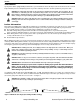
SAFETY WARNING! Do not attempt to have your power chair climb or descend an obstacle that is higher than two inches unless you have the assistance of an attendant. WARNING! Do not attempt to have your power chair proceed backward down any step, curb, or other obstacle. This may cause the power chair to tip and cause personal injury. Public Streets and Roadways WARNING! You should not operate your power chair on public streets and roadways.
SAFETY WARNING! Before transferring, position yourself as far back as possible in the power chair seat to prevent the power chair from tipping forward during transfer and causing injury. WARNING! Avoid using your armrests for weight bearing purposes. Such use may cause the power chair to tip and cause personal injury. WARNING! Avoid putting all of your weight on the footrest. Such use may cause the power chair to tip and cause personal injury.
EMI/RFI Preventing Unintended movement WARNING! If you anticipate being seated in a stationary position for an extended period of time, turn off the power. This will prevent unexpected motion from inadvertent joystick contact. This will also eliminate the possibility of unintended chair movement from electromagnetic (EM) sources. Failure to do so may result in personal injury. Prescription Drugs/Physical Limitations Users must exercise care and common sense when operating a power chair.
EMI/RFI Electric mobility vehicle motion caused by EMI/RFI can be erratic. The vehicle may move by itself or come to a sudden stop. Furthermore, it is possible for EMI/RFI to unexpectedly release the brakes on an electric mobility vehicle. Some intense sources of EMI/RFI can even damage the control system of an electric mobility vehicle.
YOUR QUANTUM DYNAMO ATS YOUR QUANTUM DYNAMO ATS Your power chair has two main assemblies: the seat and the power base. See figure 2. There are several seating options available with your power chair. Typically, the seating system includes the armrests, the seatback, the seat base, and the joystick/controller. The power base is the heart of your Quantum Dynamo ATS.
YOUR QUANTUM DYNAMO ATS Suspension: SPECIFICATIONS Active-Trac suspension Drive Wheels: Caster Wheels: 10 in., pneumatic, center-mounted (solid tires are optional) 8 in., solid, rear articulating Anti-tip Wheels: Maximum Speed: 6 in., solid, front mounted Up to 4.0 mph* Brakes: Ground Clearance: “Intelligent Braking,” electronic regenerative, disc park brake" 2.5 in. Turning Radius: Overall Size: 18.5 in. Length: 36.5 in. Seating Options: Width: 23 in.
YOUR QUANTUM DYNAMO ATS JOYSTICK/CONTROLLER HARNESS CONNECTOR MAIN CIRCUIT BREAKER BATTERY CHARGER AC POWER RECEPTACLE AMMETER Figure 3. Power Base Rear View - Electronics Tray FRONT BATTERY BOX MOTOR CONNECTORS BATTERY CONNECTORS SEAT MOUNT CONNECTORS BATTERY CAUTION LABEL REAR BATTERY BOX Figure 4. Power Base Top View 14 www.pridemobility.
YOUR QUANTUM DYNAMO ATS SEAT AND POWER BASE COMPONENTS The seating system and the power base consist of the following components. l Joystick/Controller: This device is used to move the power chair. See figure 2. l Joystick/Controller HarnessConnector: This is where the joystick harness connects to the electronics tray. See figure 3. l Armrests: These provide a comfortable place to rest your arms during time spent on your power chair. See figure 2.
COMFORT ADJUSTMENTS LIMITED ACTIVE-TRAC SYSTEM MANUAL FREEWHEEL LEVER Your power chair is equipped with a limited Active-Trac System (ATS). See figure 6. ATS is a suspension system designed to make your power chair traverse different types of terrain and obstacles while maintaining smooth operation. With ATS, your front anti-tip wheels work in conjunction with your motor suspension to help you maneuver over obstacles.
COMFORT ADJUSTMENTS To change the seat angle: You can change the seat angle by either raising or lowering the front posts or the rear posts. REMOVE SCREWS SEATBACK ANGLE ADJUSTMENT The Versa Seat seatback can be adjusted to various angles for user comfort. See figure 8. To adjust the seatback angle: 1. Use a 1/2-in. socket and a 1/2-in. wrench to remove the screws from the seatback angle adjustment bracket. 2. Position the seatback to the desired angle. 3. Reinstall the hardware.
COMFORT ADJUSTMENTS JOYSTICK EXTENSION ARMREST The joystick/controller can easily slide out away from the armrest or in toward the armrest. To extend the joystick: 1. Use a 1/8-in. hex key to loosen the setscrews in the joystick mounting block. See figure 13. 2. Slide the joystick mounting bracket into or out of the mounting block to the desired position. JOYSTICK POSITION You can position the joystick for either left-hand or right-hand use. To change the joystick position: 1.
OPERATION LOOSEN THE NUT AND BOLT ANTI-TIP WHEEL ADJUSTMENT You can adjust the anti-tip wheels so that they are higher or lower. Adjusting the anti-tip wheels also affects the stiffness of the suspension. Raising the anti-tip wheels stiffens the suspension while lowering the anti-tip wheels softens the suspension. REMOVE THE ANTI-TIP WHEEL To adjust the anti-tips: 1. Make sure the power chair is not in freewheel mode. 2. Use a 5/32-in. hex key and a 7/16-in.
OPERATION WARNING! If your power chair begins to move in an unexpected manner, immediately release the joystick. Unless the joystick is damaged, this action should stop your power chair. Keypad The keypad is located directly in front of the joystick. See figure 14b. It contains keys that you will use to control your power chair. On/Off Key The on/off keys toggles the system power on and off. WARNING! Unless faced with an emergency situation, do not use the on/off key to stop the chair.
OPERATION NOTE: When the batteries approach a discharged state, the first red light will begin to slowly flash, reminding you the batteries need to be charged immediately! Speed Settings The Remote Plus speed settings range from 1 to 5. Typically, the slowest speed setting is 1 and the fastest speed setting is 5. The settings are indicated by the number of lights that are lit. NOTE: The speed settings are preset at the factory.
OPERATION Thermal Rollback The Remote Plus is equipped with a thermal rollback circuit. This circuit monitors the temperature of the motors, power module, and remote. In the event that any of them become excessively hot (above 122° F), motor voltage is reduced. For every degree above 122° F, the voltage is reduced by 5 volts. This reduces your power chair’s speed and allows the electrical components to cool down. When the temperature returns to a safe level, your power chair resumes its normal speed.
OPERATION Joystick The joystick controls the direction and speed of the power chair. When you move the joystick from the neutral (center) position, the electromagnetic brake will release and allow the power chair to move. The further you push the joystick from its neutral position, the faster your power chair will move. When you release the joystick and allow it to return to the neutral position, you engage the electromagnetic brake. This helps the power chair decelerate and come to a complete stop.
OPERATION NOTE: If you turn on the power chair while it is locked and don’t unlock it after one minute, the power chair will automatically turn off itself. Battery Condition Meter The battery condition meter consists of six lights arranged in an arc over the battery icon. From left to right, the first two are red, the second two are orange and the last two are green. These lights give you an accurate indication of your usable battery capacity.
OPERATION Sleep Mode (If Enabled) The power chair controller features a sleep mode. Sleep mode is a built-in circuit that will automatically shut off the main power if the joystick is not moved in any direction for a period of time. This time factor is programmed into the controller. To restore power and continue, push and key on the keypad. Trouble Codes The system status light is displayed within the on/off key. This light is lit if the system is turned on.
BATTERIES AND CHARGING BATTERIES AND CHARGING BATTERIES Your Quantum Dynamo ATS uses two long-lasting, 12-volt, deep-cycle batteries. These batteries are sealed and maintenance free. Since they are sealed, there is no need to check the electrolyte (fluid) level. Deep-cycle batteries are designed to handle a deep discharge. Though they are similar in appearance to automotive batteries, they are not interchangeable.
BATTERIES AND CHARGING CAN I USE A DIFFERENT BATTERY CHARGER? You should use the charger supplied with your power chair. It is the safest, most efficient tool to charge the batteries. We do not recommend using other types of chargers (e.g., an automotive battery charger). HOW OFTEN MUST I CHARGE THE BATTERIES? Many factors come into play when deciding how often to charge the batteries. You may use your power chair all day on a daily basis, or you may not use it for weeks at a time.
DISASSEMBLY We work closely with our battery manufacturer to provide a battery that best suits the Quantum Dynamo ATS’s specific demands. Fresh batteries arrive regularly and are promptly shipped with a full charge. During shipping, the batteries encounter temperature extremes that may influence their initial performance. Heat robs the charge from the battery, and cold slows the power available and extends the time needed to recharge the battery (just as with a car battery).
DISASSEMBLY BATTERY BOXES BATTERY WELL FRAME RIGHT POWER BASE FRAME ASSEMBLY LEFT POWER BASE FRAME ASSEMBLY FRONT FRAME Figure 17. Quantum Dynamo ATS Component Assemblies DISCONNECT THE JOYSTICK/CONTROLLER HARNESS. l Disconnect the joystick/controller harness from its connector on the electronics tray. See figure 3. You may need to pull firmly and gently wiggle the harness to remove it from the connector. SEAT POST REMOVE THE SEAT.
ASSEMBLY REMOVE THE BATTERY WELL FRAME. 1. Disconnect both battery connectors and both motor connectors. See figure 4. 2. Lift and remove each battery box. See figure 20. 3. Squeeze together the latch release levers that hang vertically down from the crossbar at the rear of the battery well frame. Lift up the rear end of the battery well frame. See figure 21. Pull it to the rear of the chair to release the front slots from the locating pins on the front frame bottom bar.
ASSEMBLY CAUTION! Make certain that the front frame is snapped securely to both the right frame assembly and to the left frame assembly. INSTALL THE BATTERY WELL FRAME. 1. Hold the battery well frame so that the bottom of the well hangs downward. 2. Position the notches on the front of the battery well frame onto the locating pins on the front frame bottom bar. See figure 26. 3.
CARE AND MAINTENANCE CARE AND MAINTENANCE ROUTINE MAINTENANCE Your Quantum Dynamo ATS is a sophisticated powered wheelchair. Like any motorized vehicle, it requires routine maintenance checks. You can perform some of these checks, but others require assistance from an authorized Pride provider. Preventive maintenance is very important. If you follow the maintenance checks in this section as scheduled, you can help ensure that your power chair gives you years of trouble-free operation.
CARE AND MAINTENANCE WEEKLY CHECKS l Disconnect and inspect the joystick/controller harness from the electronics tray. Look for corrosion. Contact your authorized l l l l Pride provider if necessary. Ensure that all parts of the controller system are securely fastened to your power chair. Do not overtighten any screws. Check for proper tire inflation; there should be 30-35 psi in each tire. If a tire will not hold air, replace the tube.
CARE AND MAINTENANCE WARNING! To avoid possible injury, be sure that the controller’s power is turned off and the power chair is not in freewheel mode before performing this procedure. Follow these easy steps for a quick and safe tube or tire replacement: 1. Completely deflate the tire (if pneumatic). 2. Use a 17-mm socket wrench and driver to remove the nut from the wheel axle. See figure 27. 3. Pull the wheel off of the axle. 4. Separate the tire and tube from the rim. 5.
CARE AND MAINTENANCE CAUTION! If inspection determines excessive wear on the brushes, they must be replaced or motor damage will result. Failure to maintain the brushes could void your warranty. To inspect or replace the motor brushes: 1. Disassemble the power chair. 2. Unscrew the two screws that hold down each shroud piece. 3. Unscrew the motor brush caps. See figure 28. 4. Remove the brushes. 5. Inspect the brushes for wear. See figure 29. 6. Replace the brushes, if necessary.
OPTIONAL ACCESSORIES OPTIONAL ACCESSORIES The following accessories are available from your authorized Pride provider. POSITIONING BELT The positioning belt is designed to support the operator’s torso so that he or she does not slide down or forward in the seat. The positioning belt is not designed for use as a restraining device. Make sure the belt is secure but does not cause discomfort. WARNING! The positioning belt is not designed for use as a seat belt in a motor vehicle.
WARRANTY WARRANTY LIFETIME LIMITED WARRANTY For the lifetime of your Quantum Dynamo ATS from the date of purchase, Pride will repair or replace at our option to the original purchaser free of charge any of the following parts found upon examination by an authorized representative of Pride to be defective in material and/or workmanship: l Structural frame components TWO-YEAR WARRANTY For two (2) years from the date of purchase, Pride will repair or replace at our option to the original purchaser free of ch
WARRANTY Damage caused by: l Battery fluid spillage or leakage l Abuse, misuse, accident, or negligence l Improper operation, maintenance, or storage l Commercial use or use other than normal There is no other express warranty. Implied warranties, including those of merchantability and fitness for a particular purpose, are limited to one (1) year from the date of purchase and to the extent permitted by law. Any and all implied warranties are excluded. This is the exclusive remedy.
Quality Control - Quantum Dynamo ATS Model #______________ Serial #______________ Controller Serial # Thank you for making the Quantum Dynamo your choice in power chairs. We have thoroughly inspected your Quantum Dynamo. The following check marks indicate that it has been test driven and inspected. # In Q 1 Conuality trol Inclusion of all Parts Fit and Finish Pride keeps a more detailed report on file at the factory.