
Operation Manual


18 www.pridemobility.com Luxor
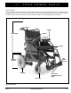
III. YOUR POWER CHAIR
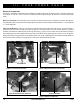
Figure 6. Controller Connection
Electrical Components
The Luxor’s controller is connected to the front battery box and to each motor. See figures 6 and 7. The motor connectors
are marked “L” and “R”. The “L” harness is connected to the left motor and the “R” harness is connected to the right
motor.
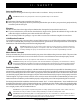
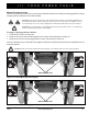
Battery Connections: The rear battery box is connected to the front battery box by the black connector. See figure 8.
The front battery box is connected to the controller by the red connector. Each connector is labeled with a “+” on one side and
a “-” on the other side.
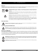
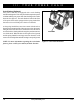
Main Circuit Breakers: There is a 30-amp circuit breaker that protects the electrical circuits. A circuit breaker is
mounted on the side of the rear battery box lid. See figure 9. The circuit breaker is in-line with the positive (+) battery
terminal. If the batteries and the motors are heavily strained (e.g., from excessive loads), the circuit breaker will trip to
prevent damage to the motors and the electronics. If the circuit breaker trips, allow the power chair to “rest” for approxi-
mately one minute. Then, push in the circuit breaker button, turn on the controller power, and continue normal operation.
If the circuit breaker continues to trip repeatedly, contact your authorized Pride Provider.
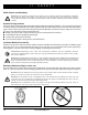
Figure 7. Motor Connection (Left Shown)
Figure 8. Front and Rear Battery Box Connection
Figure 9. Main Circuit Breaker
RED CONNECTORS
LEFT MOTOR CONNECTOR (BLACK)
FRONT AND REAR BATTERY BOX CONNECTORS
MAIN CIRCUIT BREAKER