
Operation Manual

22 www.pridemobility.com Luxor
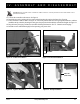
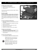
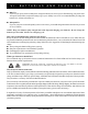
Figure 15. Battery Connection
BLACK CABLE
WHITE CABLE
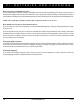
Figure 16. Battery Installation
BATTERY BOX
BATTERY BAR (SHOWN UNINSTALLED)
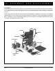
IV. ASSEMBLY AND DISASSEMBLY
To unpack and assemble the Luxor:
1. Remove the contents from the Luxor box and take
inventory. If any parts are missing, contact your autho-
rized Pride Provider immediately. See figure 13.
2. Unfold the power base assembly by pushing down on
the seat bars until they lock into place.
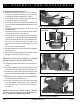
3. Install the push bar by attaching the push bar to both
seat cane handles and tightening both thumbscrews. See
figure 14.
4. Install each battery into a battery box. See VII. “Care
and Maintenance.”
5. Connect the straps to secure the battery boxes. Adjust
for tightness as necessary. See figure 16.
6. Slide the battery boxes into the battery frame. Make
sure that the “A” on the front battery box faces the front
of the power chair and the “B” on the rear battery box
faces the rear of the power chair. The main circuit
breaker on the rear battery box should be on the left
side.
7. Connect the two black connectors.
8. Install the battery bar across the rear battery and tighten
the thumbscrews.
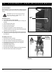
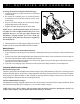
9. Remove the armrests by pushing the release button and
lifting the armrest up as shown in figure 17.
NOTE: The armrests can be flipped up by pushing
the release button on the front of the armrest.
10. Unfold the seatback and insert the canes into base as-
sembly.
11. Secure the seatback to the seat base assembly by tight-
ening the knob on each side of the chair. See figure 18.
12. Place the seat cushion on the seat base and press down
firmly. The cushion is held in place with reusable fasten-
ers.
13. Install the armrest by aligning the armrest with the posts
and sliding the armest into the posts.
14. Insert the controller into the slot under the desired
armrest and adjust to the desired position. Tighten the
lever and setscrew to secure the controller in place.
See figure 19.
NOTE: Each armrest is designed with a controller
bracket so that the controller can be mounted for ei-
ther a right-hand or left-hand application.
Figure 17. Armrest Installation
RELEASE BUTTON (SHOWN PUSHED IN)
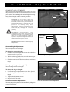
Figure 14. Push Bar Installation
PUSHBAR
HANDLE
THUMBSCREW