
Operation Manual

Luxor www.pridemobility.com 23
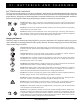
Figure 20. Leg Rest Installation
Figure 21. Anti-tip Installation
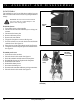
SAFETY PIN
(CLASP STYLE)
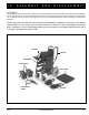
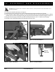
IV. ASSEMBLY AND DISASSEMBLY
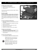
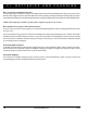
Figure 19. Controller Installation
LEVER
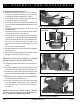
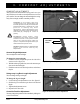
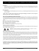
Figure 18. Seatback Installation
KNOB
WARNING! Do not place the controller cable so that it can be pinched in the seat frame or the
power base frame.
15. Connect the controller to the motors. See figure 6.
16. Install the leg rests by pushing the lever rearward and inserting the post into the frame. See figure 20.
17. Ensure the chair is in drive mode. See figure 11. If necessary, tilt the chair forward to gain ground clearance, and then
install the anti-tip wheels by inserting the safety pin (clasp style) in the desired holes at the desired height. See figure 21.
18. Plug the battery charging cord into the controller and charge the batteries. See VI. “Batteries and Charging.”
19. Read the owner's manual thoroughly before operating your power chair.
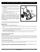
SETSCREW