
Operation Manual


34 www.pridemobility.com Luxor
VII. CARE AND MAINTENANCE
WARNING! Battery posts, terminals, and related accessories contain lead and lead
compounds. Wear goggles and gloves when handling batteries and wash hands after
handling.
WARNING! Do not replace battery when seat is occupied.
WARNING! The batteries on your power chair should only be serviced or replaced by
an authorized Pride Provider or a qualified technician.
WARNING! Power chair batteries are heavy. See specifications table. If you are unable
to lift that much weight, be sure to get help. Use proper lifting techniques and avoid
lifting beyond your capacity.
WARNING! Do not mix or match new and old batteries. If you encounter a situation
where one battery needs to be replaced, then replace both batteries. Refer to the
specifications table in this manual and the manual supplied with the battery charger
for recommended type and capacities.
To replace the batteries:
1. Turn off the power to the controller.
2. Make sure that the power chair is in drive mode. See III. “Your
Power Chair.”
3. Disconnect the controller from the motors. See figure 7.
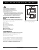
4. Disconnect the rear battery box from the front battery box. See
figure 8.
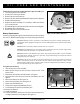
5. Remove the battery bar. See figure 30.
6. Remove the rear battery box. See figure 30.
7. Remove the front battery box.
8. Unfasten the straps from both battery boxes.
9. Lift the battery box lid off of each battery box.
10. Remove the batteries.
11. Install new batteries.
12. Connect the battery harnesses to the front and rear batteries ac-
cording to the battery wiring diagram. See figure 31.
Figure 30. Rear Battery Box
REAR BATTERY BOX
BATTERY BAR
Follow these easy steps for a quick and safe repair for solid tyres:
1. Turn off the power to the controller.
2. Set the power chair up on blocks.
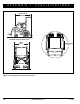
3. Remove the drive wheel nut cap.
4. Remove the drive wheel nut and washer from the axle. See figure 29.
5. Pull the wheel off the axle.
6. Replace the entire assembly if it is a solid tyre. Make sure that the
key is in the axle slot.
7. Reinstall the drive wheel nut and washer onto the axle and tighten.
8. Reinstall the drive wheel nut cap.
9. Remove the power chair from the blocks.
Battery Replacement
A battery wiring diagram is printed on a decal located on the rear battery
box. See VI. “Batteries and Charging” for correct battery specifications.
Figure 29. Drive Wheel Removal
DRIVE WHEEL NUT CAP
(SHOWN REMOVED)
DRIVE
WHEEL NUT