
Use and Care Manual

5
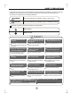
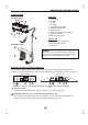
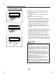
Parts names
Outdoor unit
OPERATING INSTRUCTIONS
Indoor unit
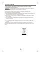
NOTE:
All the pictures in this manual are for explanation
purpose only. Your air conditioner may be slightly
different. The actual shape shall prevail.
4
3
5
2
6
1
10
9
12
13
11
7
88
1. Front panel
2. Air inlet
3. Air filter
4. Air outlet
5. Horizontal air flow grille
6. Vertical air flow louver
7. Display panel
8. Remote controller signal receiver
9. Remote controller
10. Manual control button
11. Connecting pipe, drain hose
12. Air inlet (side and rear)
13. Air outlet
Indoor unit
Outdoor unit
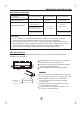
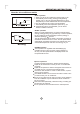
Indicator Lights on Display Window
The operation indicator lights flash rapidly (five times per second.) when safety protection
features come into operation.
The display panel of indoor unit will look like one of the following:
1
22
3
4
5
DEFROSTDEFROST TIMERTIMER
AUTOAUTO
OPERATIONOPERATION
Signal receptor
Signal receptor
1
22
3
4
5
AUTO
DEFROST
TIMERTIMEROPERATIONOPERATION
Note: For cooling only models(>18000Btu/h unit), indicator light is FAN ONLY.
22
AUTO indicator
This indicator illuminates when the air conditioner is in AUTO operation.
DEFROST indicator (For Cooling & Heating models only)
This indicator illuminates when the air conditioner starts defrosting automatically or
when the warm air control feature is activated in heating operation.
1
22
TEMP
AUTO
COOL
DRY
HEAT
FAN
HIGH
MED
LOW
MODE
FAN SPEED
SWING
TIMER O
N
ECONOM
Y
ON/OFF
TIMER O
FF
RESET LOCK
SET TEMPERATU
RE( C)
FOLLOW
M
E
LED
DISPLA
Y
ION
TURBO