
Install Instructions

4515 E. 139th Street Grandview, MO 64030 | (800) 362-9055 | PRIER.com
Installation, Operation & Maintenance Instructions for the
PRIER C-434/C-534 Self-Draining Anti-Siphon Wall Hydrant
Please leave this sheet for the property homeowner
1. Determine location for installation of the PRIER Wall Hydrant. Be assured there is adequate work room in the interior
of the structure for securing the Wall Hydrant to the interior waterline. Bore a 1 1/8” diameter hole through the wall in
the desired position for installation of the PRIER C-434/534.
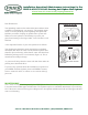
2. Always install PRIER C-434 or C-534 in the horizontal position and level. This will assure proper drainage of the
hydrant.
3. All Wall Hydrants require a slight downward pitch to assure complete draining once the valve is turned to the “off”
position. The PRIER C-434 has the proper drainage pitch built in to the hydrant’s angled backange. Simply install
the hydrant ush to a vertical wall and proper drainage pitch will be achieved.
4. Position the spout of the Wall Hydrant in the downward position. From the interior of the structure utilize the date
code on the copper pipe near the inlet. When the code is pointed down, the spout is oriented in the proper position on
the outside of the structure.
5. If planning to solder the connection (D or F Style Seats), to prevent seat damage from heat, be certain the Wall
Hydrant is in the fully open position. Overheating could cause internal damage to the stopper and factory solder joints.
6. Flush all foreign particles from the water line before connecting the Hydrant. Foreign particles may clog the vacuum
breaker / backow preventor causing it to fail. Connect the waterline to the Wall Hydrant as desired.
7. After the waterline connection is made, secure the Wall Hydrant to the structure with appropriate fasteners installed
through the screwholes.
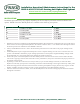
INSTALLATION
Installation procedures may vary slightly depending on the Seat Option purchased and the installation inlet
options. PRIER Freezeless Wall Hydrants are available in the following seat options:
Inlet Style Inlet Specications Hole Size
D 1/2” MPT x 1/2” SWT 1” Hole
X 1/2” Crimp PEX 1” Hole
W 1/2” Wirsbo® PEX 1” Hole
T 3/4” MPT x 1/2” FPT 1 1/8” Hole
F 3/4” SWT 1 1/8” Hole
FX 3/4” Crimp PEX 1 1/8” Hole