installation and servicing mini Your Ideal installation and servicing guide For details of document amendments, refer to page 3 Model Serial No. C24,C28,C32 S24,S28 For users guide see reverse of book When replacing any part of this appliance, use only spare parts that you can be assured conform to safety and performance specification that we require. Do not use reconditioned or copy parts that have not been clearly authorised by Ideal Boilers 17962.1062.
Mini --- Installation & Servicing
DOCUMENT AMENDMENTS Relevant Installation changes implemented in this book from book reference.................17962.1062.
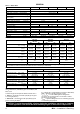
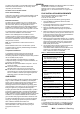
GENERAL Table 1 --- Boiler Data Mini C24 Mini C28 Gas supply type & connection Mini C32 Mini S24 Mini S28 II2H3P G20 20mbar, G31 37mbar, 22 mm copper Inlet / Outlet connection --- Domestic Hot Water 15 mm copper --- Flow & return connection --- Central Heating 22 mm copper Flue terminal diameter mm (in.) Max working pressure (sealed system) bar (lb/in2) 100 (4) Max DHW water inlet pressure bar (lb/in2) 10.0 (145.0) Min DHW water inlet pressure bar (lb/in2) 0.3 (4.4) 2.5 (36.
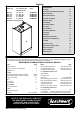
GENERAL Mini CONTENTS Boiler size G.C. appliance No. (Benchmark No.) PI No.
GENERAL BOILER WATER CONNECTION Wall mounting plate 101 (4”) 1 20 (3/4”) Pipe size O.D.
INTRODUCTION GENERAL GAS SAFETY Mini C24, Mini C28 and Mini C32 are wall mounted, low water content, balanced flue combination gas boilers. Mini S24 and Mini S28 are wall mounted, low water content, balanced flue system gas boilers. Central heating (CH) output and domestic hot water (DHW) output (on combination versions) are both fully modulating: --- between 9.10 (31 049) and 24.30 (82 912) kW (btu/h) for model Mini C24 and Mini S24; --- between 10.80 (36 849) and 28.
GENERAL The boiler must not be fitted outside. IMPORTANT Installation pipes MUST be fitted in accordance with BS. 6891. In IE refer to I.S. 813.2002. Pipework from the meter to the boiler MUST be of an adequate size, i.e. not less than 22 mm O.D. copper or 3/4” BSP iron. Timber Framed Buildings FLUE INSTALLATION REQUIREMENTS If the boiler is to be fitted in a timber framed building it should be fitted in accordance with the Institute of Gas Engineers document IGE/UP/7, 1998.
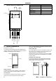
GENERAL Vertical Terminals 13 Above the roof pitch with roof slope of all angles. Above flat roof 300 mm (12”) 14 From single wall face From corner wall faces 600 mm (24”) 1000 mm (40”) 300 mm (12”) Twin Flue Applications 15 Centre distance between air inlet and flue outlet ducts 120mm (5”) *** *** Where the twin flue ducts are positioned at or near the above minimum centres the wall sealing gaskets should be trimmed to allow them to fit flat to the wall.
GENERAL 3 ELECTRICAL SUPPLY Warning. This appliance must be efficiently earthed. The point of connection to the mains should be readily accessible and adjacent to the boiler, except for bathroom installations where the point of connection to the mains MUST be situated outside of the bathroom. Wiring external to the appliance MUST be in accordance with the current I.E.E. (BS.7671) Wiring Regulations and any local regulations which apply.
GENERAL 111 litres when pressurised to 0.5 bar (cold) For expansion volumes see Table 5. 101 litres when pressurised to 0.7 bar (cold) Table 6 Mini C32 System charge pressure (bar) 0.5 0.7 Safety valve setting 3.0 Vessel pre ---charge pressure (bar) 0.7 System volume (litres) 1.0 If the pressure exceeds 2.65 bar when the boiler is up to temperature with all radiators in use then an additional expansion vessel MUST be installed on the return pipework. For expansion volumes see Table 6.
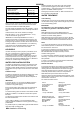
GENERAL 7 BOILER WATER CIRCUIT DIAGRAM Mini C24 --- Mini C28 --- Mini C32 22 23 24 25 21 27 20 1 33 19 18 16 15 17 14 5 31 11 8 4 Main circuit drainage cock 7 Central heating flow cock 8 By ---pass valve 9 Central heating (CH) return cock 3 18 Burner 19 Combustion chamber 21 Fan 25 22 Air pressure switch 23 Venturi device 24 Flue outlet pipe 25 Air intake pipe 33 26 Automatic air vent 18 27 Overheat thermostat 28 29 28 Pump 30 26 29 Pump vent plug 30 CH temperature probe 1
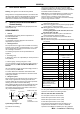
INSTALLATION BOILER ASSEMBLY --Exploded View INSTALLATION 8 1 2 3 4 5 36 6 35 7 34 33 32 31 30 8 9 16 29* 28 12 27* 13 14 P5 17 11* 26 18* 15 10 25 1 2 3 4 5 6 7 8 9 10 11 12 Venturi Fan Flue hood Flame detection electrode Overheat thermostat Primary heat exchanger Inner case cover Ignition electrodes Heat exchanger return pipe CH temperature probe DHW temperature probe Main circuit drainage cock 13 14 15 16 17 18 19 20 21 22 23 24 24 23 22 21 Auto air vent Pump Electronic control
INSTALLATION INSTALLATION 9 UNPACKING Pack B contents The boiler is supplied fully assembled in one pack A, together with a standard flue assembly for lengths up to 960 mm (37” 3/4), rear or side flue outlet, in pack B. I Air intake pipe ø 100 mm (4”) J Flue pipe ø 60 mm (2” 3/8) with terminal grille assembly K Band Unpack and check the contents. L Pack A contents M Flue pipe gaskets --- 2 off N Boiler ---turret gasket A The boiler.
11 FITTING THE FLUE SYSTEM Table 9 --- Models Mini C24, Mini S24, Mini C28, Mini S28 The maximum total equivalent lengths are given in Table 7 and Table 8 for co---axial pipes ø 60 ---100 mm, Table 9 for co---axial pipes ø 80 ---125 mm and in the diagrams for the ø 80 mm twin pipes air ---flue systems. Pipe length (ø 80/125) Restrictor Between 0,5 (19.
INSTALLATION 11 INSTALLATION For each additional 45˚ M&F and 90˚ M&F flue bend used, FITTING THE FLUE SYSTEM (cont.) Co---axial Flue kits. Horizontal. For calculation of total flue length, the distance MUST be measured from the centreline of the concentric elbow to the end of the terminal grille. Vertical outlet For calculation of total flue length, the distance MUST be measured from the centreline of the outlet connector at the boiler top panel to the end of the terminal grille.
INSTALLATION WALL MOUNTING TEMPLATE (rear flue) INSTALLATION 13 IMPORTANT Detailed installation steps are given directly on the wall mounting template 1 2 3 Tape the template into the selected position. Ensure squareness by hanging a plumbline. Mark onto the wall the following: 4 a. the wall mounting plate screw positions b. the position of the flue duct.
INSTALLATION INSTALLATION 16 FITTING THE WALL MOUNTING PLATE Refer to frame 18 for service connections. Fit the wall mounting plate Directly to the wall F Offer up wall mounting plate. F Screw through the fixing holes using 3 off no. 14x2” screws (not provided). F Check alignment with spirit level. F Tighten screws. 17 MOUNTING THE BOILER Lift the boiler onto the wall mounting plate locating the bar at the rear of the back panel assembly into the bracket.
SAFETY VALVE DRAIN Pressure relief valve The discharge pipe should be positioned so that the discharge of water or steam cannot create a hazard to the occupants of the premises or damage to electrical components and wiring. Discharge pipe 20 ELECTRICAL CONNECTIONS Warning. This appliance MUST be efficiently earthed A mains supply of 230 V ~ 50 Hz is required. Mains wiring should be 3 core PVC insulated flexible cord NOT LESS than 0.75 mm2 (24 x 0.2mm) and to BS. 6500, Table 16. (0.
22 PICTORIAL WIRING Mini C24, Mini C28, Mini C32 Wiring diagram for boiler equiped with electronic control p.c.b.
INSTALLATION PICTORIAL WIRING Mini S24, Mini S28 INSTALLATION 23 Wiring diagram for boiler equiped with electronic control p.c.b.
INSTALLATION INSTALLATION 24 FUNCTIONAL FLOW DIAGRAM Mini C24, Mini C28, Mini C32 L CH flow switch bk Gas Valve (on--- off operators) bn bu bk Fan 29 1 bu bu gy bk Safety thermostat bk 28 wh 34 rd 32 bu 33 35 gy 36 ye 8 bu 7 bn 6 bk Electronic 37 rd control pcb 38 rd 25 30 bu 26 31 bu 9 bn 11 12 13 Gas Valve (modulation coil) Three way div. valve 14 23 Air pressure switch gy bk DHW flow switch 27 DHW temp. probe NTC CH temp.
INSTALLATION FUNCTIONAL FLOW DIAGRAM Mini S24, Mini S28 INSTALLATION 25 L CH flow switch bk Gas Valve (on--- off operators) bn bu bk Fan 29 1 bu bu gy bk 28 35 gy 36 ye 25 30 bu 26 31 bu 9 bn 11 12 Gas Valve (modulation coil) 13 14 23 Electronic Air pressure switch control pcb gy bk Safety thermostat bk 27 CH temp.
INSTALLATION INSTALLATION 26 EXTERNAL ELECTRICAL CONTROLS Wiring external to the boiler MUST be in accordance with the current I.E.E. (BS.7671) Wiring Regulations. For Ireland reference should be made to the current ETCI rules for electrical installations. The fuse rating should be 3.15 AF. Route the electrical supply flexible cord and the external control flexible cord as illustrated. Lock the flexible cords in place with the clamps provided.
INSTALLATION INITIAL LIGHTING INSTALLATION 28 Mini C24 Mini C28 Mini C32 A B C D E F G Mini S24 Mini S28 Legend A Appiance operation lamps B Domestic hot water temperature control Mini C24, Mini C28, Mini C32 B Service knob Mini S24, Mini S28 Central Heating flow Domestic hot water outlet C Main switch and radiator temperature control D Boiler reset button Gas inlet Domestic cold water inlet Central Heating return Mini C shown E Lock ---out signal lamp F Programmer (optional) for Mini C24, M
INSTALLATION INSTALLATION 29 TO ADJUST PRESSURES Important: after the gas pressure checks and any adjustment operations, all of the test points must be sealed and replace the adjustment protection cap. Nomenclature of the parts on the gas valve Ignition rate adjustment A Modulation operator’s electric connectors B Minimum gas pressure adjustment C Maximum gas pressure adjustment 1 Turn on the boiler. 2 Check that the boiler lights up uniformly and adjust the ignition gas pressure, if necessary.
13 Press the reset button D repeatedly (4 times) until the lamps A give the follow indication: Mini C24 Mini C28 Mini C32 Where: Lamp ON Lamp OFF A B C D E Mini S24 Mini S28 12 Press and hold the reset button D for about 10 seconds until the lock ---out signal lamp E blinks. 30 ANTI CYCLING SETTING It is possible to set the minimum delay time that must pass between two ignitions of the burner in c.h. function mode.
INSTALLATION INSTALLATION 32 GENERAL CHECKS Make the following checks for correct operation: 1 Hot water (Mini C24, Mini C28 and Mini C32 models). a. Fully open all DHW taps in turn and ensure that water flows freely from them. b. Close all taps except the furthest one from the boiler and check that the boiler is firing at maximum rate. c. Ensure that DHW temperature of approximately 35 ˚C rise is obtained at the tap. This corresponds to a flow rate of about 10.0 (2.2) l/min (gpm) Mini C24 11.6 (2.
33 1 2 3 4 5 6 7 8 GAS CONVERSION Check that the gas cock fitted under the boiler is turned off and the appliance is switched off at the mains isolating spur. Remove the front panel of the case. Gas type Setting No. Take off the lid of the sealed chamber. Take the front panel of the combustion chamber off and remove the burner as explained in frame 37. Carry out the conversion for the type of gas, replacing the burner injectors correctly as explained in frame 45.
SERVICING SERVICING 35 SERVICING SCHEDULE To ensure the continued safe and efficient operation of the appliance it is recommended that it is checked at regular intervals and serviced as necessary. The frequency of servicing will depend upon the installation condition and usage but should be carried out at least annually. It is the law that any service work must be carried out by a registered CORGI installer. In IE, servicing work must be carried out by a competent person.
36 1 2 REMOVAL OF OUTER AND INNER CASING Turn off the gas supply at the gas service cock and disconnect the electricity supply. Remove the screws A and lift off the boiler front panel. 5 Remove the screws C and remove the boiler inner casing. C A A C 3 4 Loosen the screws B. Bring the base of the panels away from the boiler and lift them, freeing them from the top hooks.
SERVICING SERVICING 37 1 2 3 BURNER REMOVAL AND CLEANING Disconnect the electrical supply. Remove outer and inner casing (refer to frame 36). Undo the screws A and remove the combustion chamber panel B. 6 Brush off any deposits that may have collected on the burner, ensuring that the flame ports are unobstructed. Note: brushes with metallic bristles MUST NOT be used. 7 Inspect the spark and detection electrodes. Ensure they are clean and in good condition; replace if necessary.
40 RE ---ASSEMBLY 6 Refit the inner case cover. IMPORTANT. Ensure the boiler sealing panel is correctly fitted and that a good seal is made. 7 Refit the boiler side and front panels. 8 Turn on the gas supply at the gas service cock. 9 Reconnect the electrical supply. Re ---assemble the boiler in the following order: 3 4 5 Refit the burner. Reconnect the electrodes to the electronic pcb. See frame 37 for correct connectors. Refit the combustion chamber panel.
SERVICING SERVICING REPLACEMENT OF COMPONENTS 42 GENERAL THE BOILER MUST NOT BE OPERATED IF THE INNER CASE COVER IS NOT FITTED. When replacing any component: 1 Isolate the electricity supply at the switched spur. N.B. Turning the boiler “ON/OFF” switch does not isolate the live supply to the boiler. Turn off the gas supply. 2 IMPORTANT. When work is complete the inner case cover must be correctly fitted, ensuring that a good seal is made.
45 BURNER INJECTORS REPLACEMENT Injectors Burner 1 Remove the burner. Refer to frame 37. 2 Unscrew the injectors from the gas manifold. 3 Check that the new injectors are of the correct size and fit it using new gaskets. 4 Re ---assemble in reverse order. 5 Check the operation of the boiler. 46 1 SERVICING SERVICING Gas manifold OVERHEAT THERMOSTAT REPLACEMENT 2 3 Remove outer and inner casing (refer to frame 36).
SERVICING SERVICING 47 1 2 TEMPERATURE PROBE REPLACEMENT Disconnect the electrical supply. Remove the front and right hand side casing panels (refer to frame 36). Removal of CH temperature probe 3 4 To remove the CH temperature probe close off the isolating cocks of the CH circuit at the bottom of the boiler. Release system pressure by opening the main circuit drainage cock. Do not release CH pressure using the pressure relief valve. It may cause debris within the system to foul the valve.
SERVICING GAS VALVE REPLACEMENT 1 Turn off the gas supply at the gas service cock and disconnect the electricity supply. 2 Remove the front casing panel (refer to frame 36). 3 Disconnect the connectors A and B. 4 Disconnect the earth wiring from the gas valve. 5 Unscrew the connectors C and remove the pipe D 6 Unscrew the inlet connector. 7 Unscrew the screws E and remove the valve. 8 Fit the new gas valve in reverse order ensuring new gaskets are fitted and check for gas soundness.
SERVICING SERVICING 52 1 2 3 FAN REPLACEMENT If the right clearance is at least 50 cm (20”).... Disconnect the electrical supply. Remove outer and inner casing. Disconnect the connectors A and the earth connection B. 6 Unscrew the 3 screws E and remove the fan. A B F E 4 5 Disconnect the pipe which connects the venturi device to the air pressure switch. Unscrew the screws C and remove the clamp D. D 7 E Re ---assemble in reverse order. If the right clearance is less than 50 cm (20”)....
SERVICING AIR PRESSURE SWITCH REPLACEMENT Two different types of air pressure switch may be used in the boiler. Refer tho the following drawings in accordance with the type of air pressure switch used. 1 Disconnect the electrical supply. 2 Remove outer and inner casing as explained in frame 36. 3 Disconnect the pressure sensing pipe from the air pressure switch. 4 Disconnect the electrical harness from the air pressure switch.
SERVICING SERVICING 56 MAIN CONTROL PCB REPLACEMENT 1 Disconnect the electrical supply. 2 Gain access to the controls area by removing the boiler front panel and pulling the control panel (refer to frame 21). 3 Remove the screws A and remove the service panel 4 To gain access to the electronic control/ignition p.c.b. remove the screws B and remove the control panel lid. B 8 Unscrew the four screws that hold the electronic control/ignition p.c.b. on to the control panel.
Mini C24 Mini C28 Mini C32 A B C D Where: Lamp ON Lamp OFF It is now possible to check the current setting by pressing reset button D for more than 5 seconds. The three lamps A will flash a number of times corresponding to the setting of point 22. At this point only the right green light flashes. E Mini S24 Mini S28 19 Press and hold the reset button D for about 10 seconds until the lock ---out signal lamp E blinks. 20 Connect the c.h.temperature probe.
SERVICING SERVICING 57 1 2 3 4 CH FLOW SWITCH REPLACEMENT Disconnect the electrical supply. Remove the front casing panel. Remove the fork A. Open the box B and disconnect the switch. 5 Re ---assemble in reverse order. Refer to the following illustration for the correct wiring connectors on the switch C N.O.
60 1 2 3 4 5 6 DHW FILTER AND FLOW LIMITER REPLACEMENT Mini C only Disconnect the electrical supply. Remove the front panel of the case and empty the DHW circuit. Remove the flow switch A (see frame 59). Unscrew the body C and extract the flow switch group. To remove the filter B from the flow switch group separate it from the threaded ring by levering it. Re ---assemble in reverse order. A --- flow switch C --- body Flow limiter The Mini C24 model is factory fitted with a 10 litre/min. flow limiter.
SERVICING SERVICING 61 1 2 3 4 5 6 PRIMARY HEAT EXCHANGER REPLACEMENT 7 Disconnect the electrical supply. Remove outer and inner casing as explained in frame 36. Close off the isolating cocks of the CH circuit at the bottom of the boiler. Release system pressure by opening the main circuit drainage cock. Do not release CH pressure using the pressure relief valve. It may cause debris within the system to foul the valve. Remove the combustion chamber panel A by unscrewing the screws B.
62 1 2 3 4 5 6 7 DHW HEAT EXCHANGER REPLACEMENT Mini C only 8 9 Disconnect the electrical supply. Remove outer casing (refer to frame 36). Close the isolating cocks of the CH circuit and DHW supply at the bottom of the boiler. Release system pressure by opening the main circuit drainage cock. Do not release CH pressure using the pressure relief valve. It may cause debris within the system to foul the valve. Release the pressure of the DHW circuit by opening a hot tap.
SERVICING SERVICING 64 DIVERTER VALVE INTERNAL PARTS REPLACEMENT Mini C only 1 Disconnect the electrical supply. 2 Remove front and left hand casing panels (refer to frame 36). 3 Close the isolating cocks of the CH circuit and DHW supply at the bottom of the boiler. 4 Release system pressure by opening the main circuit drainage cock. Do not release CH pressure using the pressure relief valve. It may cause debris within the system to foul the valve.
67 ELECTRONIC CONTROL/IGNITION P.C.B. OPTICAL INFORMATION The following table gives a summary of the relationship between each of the possible lamp combinations and their meaning. The electronic control/ignition p.c.b. is provided with three lamps (L.E.D. indicators) A, that give optical information during the normal operation of the boiler or for service and fault fiinding purpose. Normally operating boiler C.h.
FAULT FINDING FAULT FINDING 69 FAULT FINDING With a fast pulse showing on LED 1 the boiler will continue to operate with a reduced performance in some fault conditions. WARNING Before commencing fault finding please check the following: Care must be taken when conducting fault finding tests to guard against the risk of electric shock. Are all wiring connections OK ? Are the function selector settings correct (Refer to frame 29, 30 and 33) 230 Vac is the nominal UK supply voltage.
FAULT FINDING FAULT FINDING Continued from page 48 of fault finding no With the boiler and heating circuit warm does the burner pressure reduce if the heating temperature setting is reduced to minimum? Is there between 0V dc and 16V dc at the connections on the modulating coil? (0=min, 16=max) yes Is the burner pressure within min and max value* with the boiler running? yes Combination boilers only Continued below yes no Is the continuity of the modulator harness O.
FAULT FINDING FAULT FINDING Continued from page 48 of fault finding. Is there at least one of the LEDs flashing? no no no Is LED 1 flashing with LED 2 on ? yes yes yes no Check resistance of CH temperature probe. Is it between 12 kΩ and 1.5 kΩ ? yes Repair or replace faulty wiring Continued on page 51 of fault finding Are LED2 flashing and LED 3 on? Are LED2 and LED 3 flashing? no Replace faulty thermistor Check resistance of DHW temperature probe. Is it between 12 kΩ and 1.
Are LED 1 and LED 3 flashing with LED 2 on, plus lockout LED on the fascia on? Continued from page 50 of fault finding yes FAULT FINDING FAULT FINDING Continued on page 53 of fault finding no no Rectify gas supply fault. Is there > 17 mbar at the gas valve inlet? yes yes Press reset button. Is there 230V across the Brown and Blue gas valve connection during ignition? Is there 230V at Brown and Blue at gas valve harness connector on PCB? no Is fuse continuity O.K.
FAULT FINDING FAULT FINDING Continued from page 51 of fault finding Is the burner light on? no Can the minimum burner pressure be achieved ? (Pressure values are given in Table 2 on page 4) no Adjust the burner minimum pressure refer to frame 29 yes Replace faulty PCB yes no Does the burner remain alight more than 10 seconds? yes Is the position of the detection electrode correct, and electrode undamaged? Refer to frame 43. no Rectify electrode position or replace faulty electrode.
FAULT FINDING FAULT FINDING Continued from page 51 of fault finding Is LED 1 and LED 2 flashing and LED 3 on? no Is LED 1 on and LED 2 and LED 3 flashing? no yes Replace faulty PCB Is there continuity of overheat thermostat wiring at PCB connection? no Repair or replace damaged wiring yes yes Has the main overheat thermostat operated? (Check continuity) no yes yes Allow boiler to cool and press re ---set Wait for 1 minute.
FAULT FINDING FAULT FINDING Continued from page 49 no no Is there max burner pressure* when the boiler first lights? Is there a temperature rise of 35 ˚C across the DHW circuit at: 10.0 L/min 24 kW model 11.6 L/min 28 kW model 13.1 L/min 32 kW model no Is there > 17 mbar gas pressure at the gas inlet? Rectify gas supply fault. yes yes yes Adjust the max setting on the gas valve. Refer to frame 29. Check that max burner pressure* can be achieved. no Is the maximum water flow correct 10.
The following are parts commonly required as replacements, due to damage or expendability. The failure or absence is likely to affect the safety and/or performance of this appliance. When ordering spares please quote: 1 Boiler model (see Data Plate) 2 Appliance G.C. number (see Data Plate) The list is extracted from the British Gas List of Parts which contains all available spare parts. 3 Description 4 Quantity The full list is held by British Gas, Ideal Stelrad Group distributors and merchants.
26 E69---243 Window (glass + rubber frame) 1 170977 27 169---141 1/2” flat gasket 3 075514 28 169---033 3/4” flat gasket 4 075415 Side case panel 2 174508 Control panel door 1 173637 Front case panel 1 174510 29 30 H17---563 31 1 2 6 8 4 9 P5 5 3 10 11 12 14 13 15 16 21 17 18 22 19 20 24 23 26 27 25 28 29 29 56 30 31 Mini --- Installation & Servicing
INSTALLER NOTIFICATION GUIDELINES IT IS A REQUIREMENT OF CORGI MEMBERSHIP TO REGISTER EVERY GAS APPLIANCE In addition a change to Building Regulations (England and Wales) requires the installer to notify when installing a heating appliance, as from 1st April 2005.
BENCHMARK No. GAS BOILER COMMISSIONING CHECKLIST BOILER SERIAL No. CONTROLS NOTIFICATION No.
SERVICE INTERVAL RECORD It is recommended that your heating system is serviced regularly and that you complete the appropriate Service Interval Record Below. Service Provider. Before completing the appropriate Service Interval Record below, please ensure you have carried out the service as described in the boiler manufacturer’s instructions.
Technical Training The Ideal Boilers Technical Training Centre offers a series of first class training courses for domestic, commercial and industrial heating installers engineers and system specifiers. For details of courses please ring: . . . . . . . 01482 498 432 the code of practice for the installation commissioning & servicing of central heating systems Ideal boilers P.O. Box 103, National Ave, Kingston upon Hull HU5 4JN. Telephone: 01482 492 251 Fax: 01482 448 858. Registration No.