
Instructions / Assembly

A
A
C
B
B
A
A
C
B
B
Note: Be sure to determine if latch bolt is
in the correct position before installation.
(See instructions & diagram below)
1) Slide lock housing into door frame, making sure that the radius of the latch bolt is in the
correct position.
2) Using pre-drilled holes in both top and bottom of lock housing as a guide, determine
proper location and drill two 1/8” diameter holes into the door frame. Secure lock housing
to door frame, using two of the supplied #8 self-tapping screws (A) - Diagram 3.
Do not over-tighten screws, this may cause threads to strip.
3) Position inside handle on the door and insert square spindle through door and lock
housing. Position into the outside handle.
4) Position inside handle on the other end of the square spindle. Loosely fasten inside and
outside handles together using #8 self-tapping screws provided (B)- Diagram 3, (some
movement of handles is necessary in order to complete step 5).
5) Turn the lock cam to the up position by inserting the key (if you have a double keyed
locking cylinder) or thumb turn (if you have a thumb turn and key locking cylinder). Slide
the lock cylinder thru the handles and lock housing. Secure the lock cylinder with the brass
machine screw supplied (C) Diagram 3. Check to make sure lock functions. Tighten screws
inside and outside.
6) Close screen door and mark location of latch bolt and dead bolt on door jamb.
7) In order to insure that the latch bolt and dead bolt easily enter the door jamb when the
dead bolt is in the locked position, it is necessary to remove enough wood from behind
the strike plate. Strike plate should be flushed with door jamb. Using three of the #8 self-
tapping screws supplied (Diagram 2 - page 3), secure strike plate to door jamb.
Keyed Alike: If you would like two or more doors to use the same key it is necessary to
purchase lock cylinders that are keyed alike.
K-5057 K-5057
Thumb
Turn
Thumb
Turn
Lock
Cylinder
(Optional)
Lock
Cylinder
(Optional)
Lock
Cam
Lock
Cam
Door Frame Door Frame
Interior
Handle Set
Interior
Handle Set
Exterior
Handle Set
Exterior
Handle Set
Square
Spindle
Square
Spindle
Latch
Bolt
Latch
Bolt
Dead
Bolt
Dead
Bolt
Lock
Housing
Lock
Housing
A
30°
A
30°
Diagram 1 Diagram 1
Diagram 2 Diagram 2
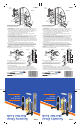
Note: The radius of the latch bolt should face the inside door
stop when door is closed.
Latch bolt may not be in the position you desire because of
right and left hand swinging doors. In order to change the
direction of the latch bolt, follow these instructions.
1) Dissasemble the handle set.
2) Press lever handle down approximately 30° and remove the single phillips screw
(A)- Diagram 1. Release the lever handle. The latch bolt is now free to be removed.
3) Rotate latch bolt 180° as shown in Diagram 1. Press down the lever handle and reinsert the
latch bolt. While handle is still depressed, replace and tighten screw (A). Release handle.
Fold at 10.875 Fold at 10.875
Note: The radius of the latch bolt should face the inside door
stop when door is closed.
Latch bolt may not be in the position you desire because of
right and left hand swinging doors. In order to change the
direction of the latch bolt, follow these instructions.
1) Dissasemble the handle set.
2) Press lever handle down approximately 30° and remove the single phillips screw
(A)- Diagram 1. Release the lever handle. The latch bolt is now free to be removed.
3) Rotate latch bolt 180° as shown in Diagram 1. Press down the lever handle and reinsert the
latch bolt. While handle is still depressed, replace and tighten screw (A). Release handle.
Latch
Bolt
Latch
Bolt
Square
Spindle
Square
Spindle
Dead
Bolt
Dead
Bolt
Lever Handle Lever Handle
Lock Housing Lock Housing
Door
Jamb
Door
Jamb
Diagram 3 Diagram 3
©2014
26950 San Bernardino Ave., Redlands, CA 92374
Manufactured to/Fabricado para/Fabriqué pour
specifications in/especificaciones
en/spécifications dans: U.S.A.
©2014
26950 San Bernardino Ave., Redlands, CA 92374
Manufactured to/Fabricado para/Fabriqué pour
specifications in/especificaciones
en/spécifications dans: U.S.A.
Web: primeline.net Web: primeline.net
7" 7"
3" 3"
30° 30°
Heavy duty diecast
Low profile
Brass plated steel strike
Heavy duty diecast
Low profile
Brass plated steel strike
Security Door
Mortise Lock
Security Door
Mortise Lock
K-5057K-5057