3 Loading the Label Stock 4 Dispensing the Label 9 Using the Control Panel 11 Label Path Diagram 12 Troubleshooting and Maintenance 13 Specifications © 2009 All rights reserved 14 Quick Start Unpacking and Setup
Notices: The information in this document is subject to change without notice. NO WARRANTY OF ANY KIND IS MADE WITH REGARD TO THIS MATERIAL, INCLUDING, BUT NOT LIMITED TO, THE IMPLIED WARRANTIES OF MERCHANTABILITY AND FITNESS FOR A PARTICULAR PURPOSE. No liability is assumed for errors contained herein or for incidental or consequential damages in connection with the furnishing, performance, or use of this material. This document contains proprietary information that is protected by copyright.
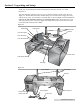
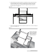
Section 1: Unpacking and Setup Thank you for purchasing the DX850 Label Dispenser (hereafter referred to as "Label Dispenser"). The Label Dispenser includes a Power Cord, 12 volt Power Adapter and the parts shown in Figure 1-1. The Roll Bar, Roll Guides and Roll Drag Arm are located in the supply box along with the Power Cord. You will need to assemble them as shown in Figure 1-1 and 1-2. Also see Section 2 for more detailed instructions on assembling these parts.
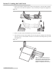
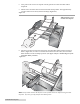
Section 2: Loading the Label Stock 1. Remove the Roll Bar and Roll Guides from the Label Dispenser. The Roll Guides and Roll Drag Arm are removable and adjustable. They are held in place magnetically. (Figure 2-1.) Figure 2-1. 2. Remove one Roll Guide and the Roll Drag Arm from the Roll Bar. 3. Place the label stock roll on the Roll Bar with one side against the upright of the remaining roll guide. Place it on the Roll Bar with the loose end of the stock feeding off the top of the roll. (Figure 2-2.
4. Place the Roll Drag Arm under the Roll Bar. The Roll Drag Arm may be placed on either side of the Roll Bar, but the rounded tip of the Roll Drag Arm should be located in the center of the inside of the core. The arm is spring loaded so that there is downward pressure on the inside of the roll. This helps prevent application alignment problems near the end of a roll. (Figure 2-3.) Figure 2-3. 5.
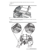
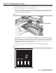
. Now position the stock to correspond with the general area where the labels will be dispensed. 7. Pull the loose end of the label stock forward under the Top Roller. Pull approximately 6 inches of label stock out beyond the Peel Edge. (Figure 2-5.) Figure 2-5. Tip! See Section 5 for a Label Path diagram. 8. Take the loose label stock and feed it between the Liner Idler Roller and the Liner Drive Roller. (Figure 2-6.
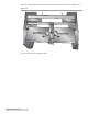
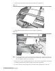
9. Pull the stock through until the Peel Edge is positioned in between two of the labels. (Figure 2-7.) Figure 2-7. Note: The liner may be fed out the front or back of the Label Dispenser. 10. Push the Liner Idler Roller into the clamped position by pressing your thumbs on the Liner Idler Roller Tabs on both sides. (Figure 2-8.) Figure 2-8.
11. Move the Label Sensor Bracket where desired within the width of the label. (Figure 2-9.) Figure 2-9. 12. You are now ready to dispense labels.
Section 3: Dispensing the Label To dispense a label, first load label stock as described in Section 2, connect power and switch on the Label Dispenser. Follow these steps to dispense labels. 1. Before you start dispensing you should adjust the Label Sensor on the Label Sensor Bracket so that the distance between the Label Sensor and the Peel Edge is equal to roughly 1/2” less than the label height. (Figure 3-1.) Figure 3-1. 1/2" less than Label Height For example, for a 4" wide x 2" high (101.6mm x 50.
3. A label will peel off the liner until it trips the Label Sensor. (Figure 3-3.) Figure 3-3. 4. Pull the label off the liner with a quick upward motion. (Figure 3-4.) Figure 3-4. Note: For labels higher than 3" (76.2 mm) you will have to slowly pull up on the label with continuous force until the end of the label clears the Guide Roller. For these type of labels set the label sensor bar to the maximum distance from the Peel Edge. 5.
Section 4: Using the Control Panel The Control Panel can be used to start and stop dispensing of labels, display label counts and other advanced functions. Start/Stop Button: Starts or stops the motor depending on whether or not the label sensor is tripped. Note: If sensor does not get triggered in a 24” run, the motor will stop. a. If the motor is in Stop Mode the display flashes. Otherwise the display is on solid. b.
Section 5: Label Path Diagram Label Path Diagram Label Path Liner Drive Roller Liner Idler Roller Peel Edge Front or Rear Liner Output 12 DX850 Label Dispenser
Section 6: Troubleshooting and Maintenance Troubleshooting Motor stalling on labels 6" (152 mm) or wider. For label stock 6” (152 mm) and wider, it may be necessary to reduce the speed of the Label Dispenser. The Label Dispenser includes a Half-Speed Mode that generates more power from the motor for wider label stock. To activate this mode, hold down the - Button while switching on the unit. The Label Dispenser will revert back to the Default Mode when switched on without holding down the - Button.
Section 7: Specifications Supply roll diameter: Up to 8" (203mm) Label width: 0.75" to 8.25" (19.1mm to 209.6mm) Media liner width: 1.00" to 8.38" (25.4mm to 213.0mm) Label height/length: 0.75" to 24.00" (19.1mm to 609.6mm) Supply roll core: 2" to 3" (51.8mm to 76.2mm) ID Electrical rating: 12 VDC, 5.0 A Power requirements: 100-240 VAC, 50/60 Hz, 60 watts Feed speed: 4 in/sec. in Default Mode 2 in/sec. in Half-speed Mode for 6-8" wide labels See Section 4.
P/N 511260 - 052609