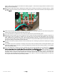
Primus Wind Power AIR Circuit Replacement Instructions Items included with this kit: (see Exploded View p.
Important notes before you begin: PLEASE READ ALL OF THE INSTRUCTIONS BEFORE BEGINNING THE UPGRADE PROCEDURE. Pay attention to the tightness of each bolt as you remove it in order to get a feel of how tight they need to be when the parts are reinstalled. Be careful not to over-tighten. PERFORM ALL TESTING PROCEDURES PRIOR TO RECONNECTING TURBINE TO BATTERY SUPPLY.
ECO 101-2720 05/17/2012 Page 3 of 12 3-CMLT-1016 REV G
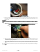
1. Disconnect the wires and remove the turbine from the mount as per the AIR X or AIR BREEZE Owner’s Manual, 5 Section 6. Remove the nose cone, then the blade assembly with a /16” hex key. 5 2. Using the /32” hex key, remove the three screws from the face of the turbine. 3. Remove the face by using a small flat head screwdriver to pry open the front. If it is a marine unit, be careful not to damage the powder coating. Remove and discard the old o-ring.
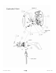
Fig. 2 c.) With the yaw shaft assembly removed, use a ¼” socket or nut driver to remove the two screws holding the circuit to the body casting. These are the screws on the left and right side of the solid metal rectifier (item 13 on exploded view). METHOD #2 Important note: snap ring must remain in place for this method. If you removed it in attempt to use method #1, replace it now. a.) Remove the bolt, washers, and fiberglass spacer from the top of the slip ring assembly using a 10mm box-end wrench.
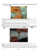
Fig. 4 10. Unclip the ribbon cable from the circuit. See Fig. 4 11. Use a 5/16” socket or nut driver to remove the potentiometer nut on the side of the unit. (The socket or nut driver may need to be modified by grinding or filing it to make a thinner wall of material on the tool. This will allow it to fit into the body contour to remove the nut.) 12. Gently push the potentiometer from the unit. The potentiometer should give way very easily. Clean the excess silicone off of the turbine. 13.
18. Place the new AIR X or AIR BREEZE circuit next to the front of the body. Holding the ribbon cable, carefully separate the two LED wires, as a pair, from the potentiometer wires. Leave about 7” of ribbon cable intact (in the five wide form) from the circuit. See Fig. 6 Fig. 6 19. Straighten out the wires that lead to the LED by running it between your thumb and index finger. Gently squeeze the wires near the LED together to allow it to properly fit into the LED clip. Do not attach the clip yet. 20.
default setting for the internal regulator. See Fig. 8. (The new circuit and potentiometer are preset to the factory voltage setpoint. For instructions on adjusting the potentiometer to change the regulation voltage, see section 7-3 in your AIR BREEZE owner’s manual or section 4.4 in your AIR X owner’s manual.) Holding the potentiometer only from the inside, being careful not to hold onto the potentiometer wires, tighten the nut until the potentiometer is snug.
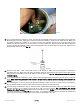
down to make sure the springs and brushes are working together. Check that the spring remains vertical and is not sliding out of the rectifier slot. 32. Make sure the bottom brush wire is between the rectifier and the circular ground sleeve on the body casting. A small screwdriver may be necessary to push this wire into its proper position. Be sure that the brush moves freely inside the slot. See Fig 10. Fig. 10 33. Insert the ground brush and spring into the circular ground sleeve on the body casting.
Fig. 11 39. If you used method #2 to replace the circuit, push the slip ring assembly back into its proper position on the yaw shaft while keeping the brushes depressed in their slots behind the assembly. A small pick can assist with this. Make sure the plastic insulating tube remains in the center of the slip ring assembly and that none of the wires get pinched between the slip rings – failure to do so may result in a short and malfunction.
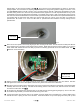
PIC Chip Brush Tracks Fig. 13 44. Carefully snug each of the three stator wire mounting screws ensuring that the connectors maintain the correct alignment. DO NOT over-tighten these screws as the threads are easy to strip. Tighten the screws to the point where a light push in either direction on the ring terminal does not rotate the screw or ring terminal (approximately 10 in-lbs of torque). 45. Spin the rotor by hand to check for a short-circuit.
51. Re-mount the blades to the blade hub as described in your AIR X or AIR BREEZE owner’s manual. Tighten the screws to 10 ft-lbs (13.6 Nm). Note: Nylock nuts may only be used one time; replace after each use. 52. Important note: AIR X and AIR BREEZE blades must not be used interchangeably as future replacement blades, as they are specifically designed to work with the circuitry of each turbine. If the turbine is to be installed on a “tilt-up” tower mount the blade/hub assembly to the turbine now.