
Primus Air 30 Circuit Replacement Kit Instructions

ECO 101-2720 05/17/2012 Page 4 of 12 3-CMLT-1016 REV G
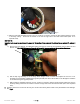
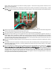
1. Disconnect the wires and remove the turbine from the mount as per the AIR X or AIR BREEZE Owner’s Manual,
Section 6. Remove the nose cone, then the blade assembly with a
5
/
16
” hex key.
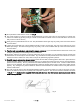
2. Using the
5
/
32
” hex key, remove the three screws from the face of the turbine.
3. Remove the face by using a small flat head screwdriver to pry open the front. If it is a marine unit, be careful not to
damage the powder coating. Remove and discard the old o-ring. The stator, rotor, and face should come off as a
single assembly
4. If the face casting comes off and the stator remains in the body, firmly grasp the rotor shaft with one hand and the body
of the unit with the other hand and pull the rotor straight out. Moderate force will be necessary to overcome the
magnetic field that holds the rotor inside the stator. Use a flathead screwdriver to pry the stator from the body. This is
done by inserting the blade of the screwdriver into one of the three recessed areas where the stator meets the body of
the unit, and carefully prying the stator out a little bit. Work your way around the stator prying little by little at all three
of the recessed points until the stator is removed.
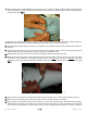
5. Carefully note the routing of the wires connecting the stator windings to the circuit board. Note the parallel orientation
of the three stator ring-terminals and how they are isolated from one another. Also, take note of the circuit and the way
it is positioned inside the body. Note how the yaw shaft is seated in the bearing and how the brushes make contact
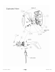
with the slip rings behind the yaw shaft. Take note of the Exploded View at the beginning of this document for part
identification.
6. Attach the anti-static strap to your wrist per the instructions on the strap package.
7. Using a 7/64” allen key, remove the three small screws connecting the stator wires to the circuit. NOTE: (It is very
easy to strip the threads on these screws when reattaching the stator wires. Try to get a feel for the factory torque
setting (10 in-lbs) on these bolts. They will need to be reattached in the same manner.)
8. It is possible to use two methods to remove the circuit:
METHOD #1
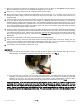
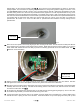
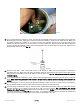
a.) Using the external snap ring pliers, remove the snap ring from its groove located below the slip rings on the yaw
shaft assembly. A screwdriver may assist in the removal of the snap ring. See Fig. 1
Fig.1
b.) Once the snap ring is removed, use a hammer and a blunt object or a plastic mallet to drive the yaw shaft
assembly out by hitting it on the top end of the slip ring assembly, or use a screwdriver to separate the yaw shaft
assembly from the body. This may take a little effort; so be careful. As the yaw assembly is removed, watch
closely for the earth-ground brush and spring as they may release and be difficult to find. See Fig. 2
VERY IMPORTANT: If the yaw shaft requires more than moderate force to remove, or if there is concern for th e
well-being of the balance of components due to the force that is necessary to remove the yaw shaft, try using
method #2. DO NOT attempt to force the yaw shaft out of the body. Damage to the body, yaw shaft, or both may
result. Contact Primus Wind Power (303-242-5820 x 103) or nearest representative for advice on how to proceed or
for alternate solutions to the replacement of the circuit. You may be asked to return the unit to the factory for repair.