
Primus Air 30 Circuit Replacement Kit Instructions

ECO 101-2720 05/17/2012 Page 6 of 12 3-CMLT-1016 REV G
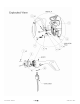
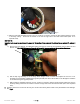
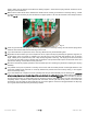
Fig. 4
10. Unclip the ribbon cable from the circuit. See Fig. 4
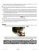
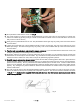
11. Use a 5/16” socket or nut driver to remove the potentiometer nut on the side of the unit. (The socket or nut driver may
need to be modified by grinding or filing it to make a thinner wall of material on the tool. This will allow it to fit into the
body contour to remove the nut.)
12. Gently push the potentiometer from the unit. The potentiometer should give way very easily. Clean the excess silicone
off of the turbine.
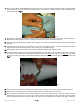
13. Lightly tap the LED with end of the screwdriver handle to push it into the body. Tap only on the LED and not on the
black clip holding it. The LED should give way very easily. Pull out the old black LED clip. Clean the excess silicone
off of the turbine.
14. Turn the body open-side down and shake it to remove any debris. If you used method #2 to remove the circuit, hold
the slip ring assembly to avoid damage to the wire insulation.
15. Thoroughly clean the flat surface on the body where the circuit is mounted. It is very important that the contact area
between the circuit and body be free from debris. Any miscellaneous metal particles in this area could short-circuit the
turbine and cause a malfunction. Also, clean the top of the yaw bearing if grease is present.
16. Carefully unpack and examine the new circuit. Check that the small, insulating plastic tubes are in place within the
screw holes which attach the board to the body casting. If any pieces are missing from the circuit or the bolt packages,
please contact the factory. Be very careful with the rectifier insulator pad on the new circuit. Check to make sure the
pad is not cut or damaged. The pad must electrically insulate the rectifier from the body in order for the turbine to work
properly. Any damage to the pad that allows an electrical contact between the rectifier and the body will cause the
turbine to malfunction.
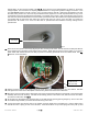
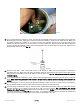
17. The new circuit will have a wire harness/potentiometer already connected. Should you need to reconnect it for any
reason, be aware that the clip has a polarity that is important to observe. The correct connection orientation is shown
in Fig. 5 below. Each circuit is supplied with its own wire harness – the wire harness must only be used with the
circuit it is supplied with.
Fig. 5