
Primus Air 40 & Breeze Circuit Replacement Kit Instructions

ECO 101-2720 05/17/2012 Page 11 of 12 3-CMLT-1016 REV G
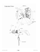
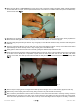
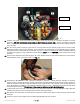
Fig. 13
44. Carefully snug each of the three stator wire mounting screws ensuring that the connectors maintain the correct
alignment. DO NOT over-tighten these screws as the threads are easy to strip. Tighten the screws to the point
where a light push in either direction on the ring terminal does not rotate the screw or ring terminal (approximately 10
in-lbs of torque).
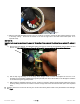
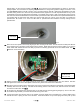
45. Spin the rotor by hand to check for a short-circuit. If the rotor does not spin smoothly (cogs), then the circuit is either
improperly installed or the circuit is defective. In the case where the turbine does not spin smoothly (cogs), check the
stator wires and the rectifier plate for any indication of a short. In order to understand the difference between spinning
smoothly and cogging, it is best to perform a cog test. Perform step 1 from the TESTING section toward the end of this
document.
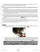
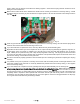
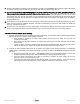
46. Push the three stator wires into the body at the 12 o’clock position (when the yaw shaft is toward you) so they will not
interfere with the circuit, yaw shaft, or rotor. See Fig. 14
Fig. 14
47. Assemble the AIR BREEZE or AIR X alternator assembly to the body. Loosely place the alternator on the body
opening in such a manner that the wire bundle of the stator is oriented toward the top of the body casting. Slowly re-
orient the alternator assembly to align the alternator mounting bolt holes of the face with the mounting holes in the
body. Be sensitive to “grabbing” of the alternator assembly during this step. Grabbing may indicate the stator wires
are interfering with the circuit. Wound stator wires must not make contact with the body casting.
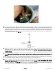
48. Loosely thread in the face bolts. Place the black O-ring around the perimeter of the AIR BREEZE or AIR X alternator
assembly and loosely fit it into to the gap between the face and body castings.
49. Spin-test the rotor shaft again, to ensure that the resistance to rotation is the same as it was during the open face test
in step 45.
50. Once the O-ring is in place tighten the 3 face bolts (approximately 35 in-lbs of torque)
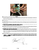
PIC Chip
Brush Tracks