
Primus Air 40 & Breeze Circuit Replacement Kit Instructions
ECO 101-2720 05/17/2012 Page 12 of 12 3-CMLT-1016 REV G
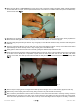
51. Re-mount the blades to the blade hub as described in your AIR X or AIR BREEZE owner’s manual. Tighten the screws
to 10 ft-lbs (13.6 Nm). Note: Nylock nuts may only be used one time; replace after each use.
52. Important note: AIR X and AIR BREEZE blades must not be used interchangeably as future replacement blades, as
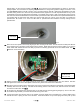
they are specifically designed to work with the circuitry of each turbine. If the turbine is to be installed on a “tilt-up”
tower mount the blade/hub assembly to the turbine now. Slide the hub onto the shaft. Start the 5/8-18 hub nut on the
shaft threads and “spin” the hub completely onto the turbine alternator shaft. Fully tighten the hub to 50 ft-lbs (68 Nm)
by inserting a 5/16 inch hex key wrench in the turbine alternator shaft and turning the shaft while turning the blades in
the opposite direction.
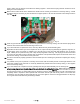
53. If the turbine is to be installed after the tower is erected, it will be safer and easier to first install the turbine body on the
tower and then install the hub/blade assembly. This will avoid attempting to mount the turbine while the blades are
spinning – a dangerous condition.
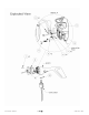
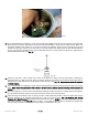
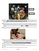
54. Snap the nose cone into position over the outside edges of the blade hub. Make sure all three edges of the nose cone
snap over the edge of the blade hub. After installation tug on the nosecone to make sure it is securely attached.
TESTING: To test the turbine, do the following:
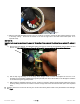
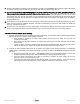
1) Spin the shaft by hand so that it is spinning very fast. Periodically touch the black and red yaw wire together while
spinning the rotor for a sample of the regulation resistance.
a. There should be resistance to rotation while spinning the rotor when the black and red wires are
contacting one another.
b. There should be very little resistance to rotation while spinning the rotor with the black and red wires
disconnected.
c. If there is cogging, or braking resistance while spinning the rotor with the wires disconnected, then there is
a short-circuit in the unit. In this case, remove the face and attempt to locate the short.
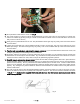
2) Connect the red and black turbine wires to the positive and negative of the battery terminals or an adjustable
voltage supply. Immediately upon making the battery connection, the AIR X / AIR BREEZE LED light should blink
two times.
a. During these two blinks, the AIR X / AIR BREEZE applies the internal electrical brake, and the rotor
should be extremely hard to rotate. After the two blinks, the rotor should again spin freely.
b. If the LED does not blink when the turbine is connected to a battery or power supply, the circuit is
defective or there is an internal open-circuit.
c. If the rotor shaft spins freely during the first two LED blinks, the circuit is defective. If the circuit does not
spin freely after the first two blinks, the circuit is defective or there is an internal short-circuit.