
Primus Air 40 & Breeze Circuit Replacement Kit Instructions

ECO 101-2720 05/17/2012 Page 5 of 12 3-CMLT-1016 REV G
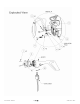
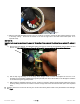
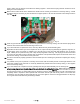
Fig. 2
c.) With the yaw shaft assembly removed, use a ¼” socket or nut driver to remove the two screws holding the circuit
to the body casting. These are the screws on the left and right side of the solid metal rectifier (item 13 on
exploded view).
METHOD #2
Important note: snap ring must remain in place for this method. If you removed it in attempt to use method #1, replace it
now.
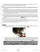
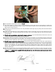
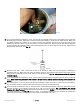
a.) Remove the bolt, washers, and fiberglass spacer from the top of the slip ring assembly using a 10mm box-end
wrench. See Fig.3 NOTE: New circuit boards will have this large capacitor on the opposite side shown.
Fig.3
b.) Pull the slip ring assembly out of the body, which will give room to remove and replace the circuit. It is not
necessary to pull the wires completely through the yaw shaft, but care must be taken not to damage the insulation
on the wires during the upgrade process.
c.) With the slip ring assembly removed, use a ¼” socket or nut driver to remove the two screws holding the circuit to
the body casting. These are the screws on the left and right side of the solid metal rectifier (item 13 on exploded
view).
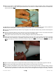
9. Carefully remove the circuit from the body as it is still connected by ribbon cable to the potentiometer and LED light.
See Fig. 4