
Primus Air 40 & Breeze Circuit Replacement Kit Instructions

ECO 101-2720 05/17/2012 Page 8 of 12 3-CMLT-1016 REV G
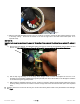
default setting for the internal regulator. See Fig. 8. (The new circuit and potentiometer are preset to the factory
voltage setpoint. For instructions on adjusting the potentiometer to change the regulation voltage, see section 7-3 in
your AIR BREEZE owner’s manual or section 4.4 in your AIR X owner’s manual.) Holding the potentiometer only from
the inside, being careful not to hold onto the potentiometer wires, tighten the nut until the potentiometer is snug. If it is
not possible to keep the slot aligned with the dimple or if a dimple does not exist, make a new dimple (using a punch)
and orient the slot as described above and mark it with a permanent marker. Be careful that the potentiometer wires do
not interfere with the LED wires and make sure that the LED does not pull out of the clip when you tighten the
potentiometer. Be careful not to crush the LED wires or potentiometer wires between the body casting and the
potentiometer.
Fig. 8
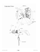
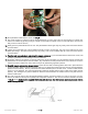
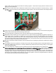
27. Place the circuit in position in the body aligning the two mounting screw holes. Ensure that the insulator pad adheres
to the rectifier and is not peeled or bent away from the rectifier. While orienting the circuit in the turbine, try to tuck the
ribbon cable down towards the tail of the body to prevent it from being pinched as the circuit is bolted down. See Fig.
9 below for correct orientation.
Fig.9
28. Tighten the two screws so they snugly secure the circuit to the body, approximately ¼ turn once seated. DO NOT
over-tighten the screws as the white plastic insulators may distort and cause future malfunction.
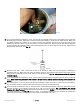
29. Ensure that the ring terminal at the attachment point of the red brush wire attached to the bottom of the metal rectifier
assembly does not touch the body. This will connect battery positive to the turbine case, will short-circuit the turbine,
and cause a malfunction. See Fig 9.
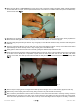
30. At this point it is advantageous to stand the body on end with the body opening pointing straight up. Sit in a firm chair
and hold the body between your knees with the tail resting on the floor.
31. Lift the two brushes from the two slots on the rectifier using the dental pick or equivalent tool. Insert a plastic spring
standoff and then a spring in each of the two slots. Place the brushes on top of the springs and then push up and
Ring Terminal on
positive brush
wire (note 29)
Align slot
with dimple