
Primus Air 40 & Breeze Circuit Replacement Kit Instructions

ECO 101-2720 05/17/2012 Page 9 of 12 3-CMLT-1016 REV G
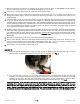
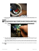
down to make sure the springs and brushes are working together. Check that the spring remains vertical and is not
sliding out of the rectifier slot.
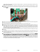
32. Make sure the bottom brush wire is between the rectifier and the circular ground sleeve on the body casting. A small
screwdriver may be necessary to push this wire into its proper position. Be sure that the brush moves freely inside the
slot. See Fig 10.
Fig. 10
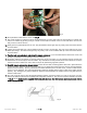
33. Insert the ground brush and spring into the circular ground sleeve on the body casting. Be sure that the spring side is
inside the hole and the solid brush is extending from the hole.
34. If you used method #1 to replace the circuit, clean any debris from the yaw shaft bearing seat.
35. Regardless of which method you used to replace the circuit, inspect the slip ring assembly for tightness, alignment, or
unusual wear. Clean any grease or oxidation off of the slip rings on the yaw shaft with abrasives such as: Scotch
bright, a Brillo pad or a piece of Emery cloth. Wipe the slip rings with a clean rag. The slip rings should not be buffed
to a shine, but clean with the fine scratches from the abrasives. This procedure will improve the electrical contact and
promote the “seating” of the brushes and the yaw shaft.
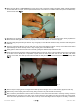
36. Ensure that each brush properly operates in its brush holder prior to re-inserting the yaw shaft or replacing the slip ring
assembly.
37. It is possible at this point to perform a continuity test to ensure that the rectifier pad was not damaged when the new
circuit was installed: there should be no continuity between the positive brush and the body casting, or the negative
brush and the body casting.
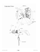
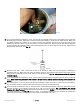
38. If you used method #1 to replace the circuit, partially insert the yaw shaft assembly into the bearing hole. Place the
external snap ring just over the slip rings of the yaw shaft prior to setting the brushes. While holding each brush in
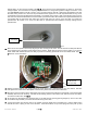
its respective guide, insert the yaw shaft into the hole the rest of the way. See Fig. 11. Secure one brush at a time as
the yaw shaft is inserted. A rubber mallet may be necessary to tap the yaw shaft in place once all of the brushes are
completely seated. Repeat the same operation with each brush until the yaw shaft is fully seated. Use caution with
the brushes, they are brittle and may break with too much force applied. Ensure that the gaps between the slip rings
do not “grab” the brushes while the yaw is being installed.