PROFESSIONAL WASHER EXTRACTORS 6kg 7,5kg SOAP HOPPER ON TOP PANEL ORIGINAL INSTALLATION, MAINTENANCE AND USER'S MANUAL 516574 C Publication date: 3 Nov 2009
USER'S MANUAL 1. TABLE OF CONTENTS 1. TABLE OF CONTENTS ................................................................................................ 1 2. WARNINGS AND LABELS ........................................................................................... 2 2.1. INSTRUCTIONS FOR MAINTENANCE, ADJUSTMENT AND SAFETY OF PEOPLE .........................3 3. SYMBOLS ON THE MACHINE ..................................................................................... 4 4. OPERATION INSTRUCTIONS......
2. WARNINGS AND LABELS TO MINIMIZE THE RISK OF FIRE, INJURY BY ELECTRIC SHOCK OR SERIOUS INJURIES TO PEOPLE OR PROPERTY DAMAGE, PLEASE READ AND FOLLOW THE FOLLOWING INSTRUCTIONS: – This English version is original language version. Without this original version, these instructions are incomplete. – Before installation, operation and maintenance of the machine read carefully the complete instructions, i.e. this „Installation, maintenance and user's manual“, „Programming manual“ and „Spare parts manual“.
WARNING! Always disconnect the washer from the electrical supply before attempting any service. The washer extractor is out of tension if the main plug is taken out or when the main supply is disconnected. When the main switch is turned off the inlet terminals of the machine main switch are still under current! CAUTION! Extreme hot conditions can arise in the surroundings of this air. Watch out for vapor that escapes from the washer extractor venting! CAUTION! Do not cover the washer extractor venting.
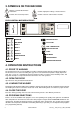
3. SYMBOLS ON THE MACHINE Danger, read and follow written instructions Caution, high power voltage, electrical devices Caution, increased temperature Caution, outlet of steam from the machine EASY CONTROL MICROPROCESSOR PREWASH PROGRAM SELECT MAIN WASH CYCLE TIME RINSE 1 COIN / TEMPERATURE RINSE 2 FUNCTION BUTTON RINSE 3 START EXTRACT RUN MODE DOOR RELEASE PROGRAM MODE FAULT DOOR OPENING BUTTON 4. OPERATION INSTRUCTIONS 4.1.
4.6. ADD DETERGENTS 101008 Dispenser A: Prewash (add the detergent at the beginning of the wash cycle). Dispenser B: Wash (add powder detergent or bleach detergent at the beginning of the cycle, you may add liquid detergent or liquid bleach during the wash cycle. If added at the start of the cycle, it will run in the washer prematurely). Dispenser C: Final Rinse (Add fabric softener at the beginning of the cycle or before the final rinse). R Standard wash programs versus custom made wash programs.
5. FIRST SERVICE AT TECHNICAL PROBLEM IMPORTANT! TECHNICAL INTERVENTION ON THE WASHING MACHINE IS ONLY FOR QUALIFIED TECHNICIANS WITH SUFFICIENT TECHNICAL KNOWLEDGE OF THE „EASY CONTROL“ WASHING MACHINE. FAILURE 1: DRAIN FAILURE NOT FINAL SEQUENCE Failure 1 occurs when the electronic timer detects that the water is not drained after 3 minutes in a drain or spin step. The failure message is displayed at the end of the cycle. DIAGNOSE: 1. Check the drain tube of the washing machine. 2. Check the drain valve.
FAILURE 5: OUT OF BALANCE HIGH SPIN Failure 5 occurs when the out of balance sensor is activated at high spin. This failure indicates that there will be probably a mechanical defect. DIAGNOSE: 1. Check the position of the out of balance switch. 2. Check the springs and the other mechanical parts that fix the drum. 3. Check the wiring if there is a bad connection. If the out of balance switch is not correctly mounted, install the out of balance switch properly.
FAILURE 14: HEATING TIME FAILURE When after 75 minutes the target temperature is not reached (for a machine set as wait for heat): Message 14 will be displayed. DIAGNOSE: 1. Check if the heating resistors are heating 2. Check the water temperature 3.
INSTALLATION AND MAINTENANCE MANUAL 1. TABLE OF CONTENS 1. TABLE OF CONTENS .................................................................................................. 1 2. IMPORTANT SAFETY INSTRUCTIONS....................................................................... 2 2.1. DURING TRANSPORTATION AND STORAGE..................................................................................3 2.2. MACHINE SYMBOLS ......................................................................................
2. IMPORTANT SAFETY INSTRUCTIONS WARNING - SAVE THESE INSTRUCTIONS FOR LATER USE. Failure to comply with the instructions may lead to incorrect use of the appliance, and may result in risk of fire, bodily injuries or death and/or damage to the laundry and/or the appliance. WARNING - read the IMPORTANT SAFETY INSTRUCTIONS in this manual carefully before operating the appliance.
2.1. DURING TRANSPORTATION AND STORAGE DURING TRANSPORTATION AND STORAGE NEVER PUSH, PULL OR EXERT PRESSURE ON COMPONENTS PROTRUDING FROM THE CONTOUR LINE OF THE MACHINE (CONTROL ELEMENTS, DOOR LOCKS ETC.). MAKE SURE THAT THESE PARTS ARE SECURED TO AVOID ANY DAMAGE DURING MANIPULATION AND INSTALLATION. If transportation is provided by the customer it is necessary to follow the manufacturer´s instructions concerning transportation, handling and storage.
3. TECHNICAL INFORMATION 3.1.
HEATING Types of heating: cold soft / hot soft water - without electric heating cold soft / additional hot soft water - with electric heating 2750 W - with electric heating 6000 W - with electric heating 9000 W CONNECTION WATER CONNECTION: water pressure water inlet maximal water temperature CONNECTION OF WATER DRAINAGE: via drain valve diameter flow amount with drain valve via drain pump, hose diameter flow amount with drain pump Soap hoppers: 0.1 - 0.8 MPa / 1-8bar / 14.
6 kg / 15 lb 7,5 kg / 18 lb 12. „Program/run“ mode push button 13. Serial plate 14. Fuses 15. Electrical connection of the machine 16. Plug 17. Hose orifice of the version with drain pump 18. Drain of the version with drain valve 19. Adjustable leg 20. Soap hopper 21. Liquid soap hose connections 22. Plastic box for electrical connection to liquid soap pumps Fig. 3.1. Dimensions and components of the machine 1. Door open push button 2. F push button 3. START push button 4. Card of wash programs 5.
4. MACHINE INSTALLATION 4.1. MANIPULATION AND UNPACKING DURING TRANSPORTATION All doors and passages the machine is to be transported through during installation must be reasonably dimensioned to meet the width, height and depth off the machine including the package. The machine dimensions are stated in chapter „3.Technical information“. UNPACKING If possible, leave the machine in transporting package until the machine connection in the laundry. The machine is screwed to the skid by two bolts M10x60, fig.
! WARNING! IF THE MACHINE IS LOCATED ON A HIGHER BASE FOR BETTER OPERATION, THE FRONT LEGS OF THE MACHINE SHOULD BE LOOCKED FOR SAFETY REASONS (SEE FIG. 4.3.). Do not forget to leave an access space to the lever of emergency door opening (fig.4.3.,pos.2), which is located in the bottom left front machine part. 1. U-profile 2. Lever of emergency door opening Fig.4.3. Bottom machine frame 4.4.
4.5. CONNECTION ELECTRICAL CONNECTION ! WARNING! THE MACHINE MUST BE CONNECTED TO THE POWER, GROUND, WATER, VENTILATION AND STEAM SUPPLY ACCORDING TO THE INSTALLATION MANUAL, IN COMPLIANCE WITH THE VALID LOCAL STANDARDS DONE BY QUALIFIED TECHNICIANS WITH PROPER AUTHORIZATION. THE VALID STANDARDS FOR CONNECTING TO THE LOCAL POWER NETWORK (TT / TN / IT, ...) MUST BE FOLLOWED. IN THE STANDARD EXECUTION, THE WASHER MAY NOT BE SUITABLE FOR CONNECTING TO AN IT SUPPLY SYSTEM.
INSTALL SUPPLY CABLE TO THE MACHINE ! WARNING! THE PROTECTIVE CONDUCTOR MUST BE LONGER SO THAT WHEN THE CABLE IS PULLED OUT ACCIDENTALLY, THIS CONDUCTOR IS DISCONNECTED AS THE LAST ONE! 4. Black - phase conductor 5. Black - phase conductor 1. Green-yellow - protection conductor PE 2. Brown - phase conductor 3. Blue - neutral conductor N 3AC 440V 3AC 220-240V 1AC 220-240V / 50/60Hz 3AC+N 380-415V Fig.4.5.A.
WATER DRAIN CONNECTION The machine is equipped with drain valve or optional with pump. – for the machine equipped with drain valve; connect the drain pipe to the drain valve by means of included clamp. The main drain pipe must have the capacity to be able to handle the total output of all connected machines. – for the machine equipped with drain pump; connect the end of the drain hose to a siphon or via a wash basin / sink. The hose must be laid out without kinks.
ELECTRICAL CONNECTION The power supply of the liquid soap supply system has to be connected to an external electrical source. Only authorized workers with a valid qualification must execute the electrical connection on the machine according to the valid local standards. The correct connection way can be found on the wiring diagram that is located inside the cabinet in a plastic bag. Do not connect the liquid soap pump system in the washer.
5. MAINTENANCE AND ADJUSTMENTS ! WARNING! ALWAYS FOLLOW SAFETY INSTRUCTIONS! DO NOT BYPASS ANY SAFETY DEVICES OR THEIR PARTS. ANY INTERFERENCE TO THE MACHINE FUNCTIONS AND CONSTRUCTION ARE PROHIBITED! USE THE PROPER CHEMICAL AGENTS WHICH AVOID CALCIUM SEDIMENTS ON HEATING ELEMENTS AND OTHER MACHINE PARTS. DISCUSS THIS ISSUE WITH YOUR SUPPLIER OF WASHING PRODUCTS. THE MANUFACTURER OF THE MACHINE IS NOT RESPONSIBLE FOR THE DAMAGE OF HEATING ELEMENTS AND OTHER MACHINE PARTS DUE TO CALCIUM SEDIMENTS.
1. Plug of emergency drain 2. Pump cover Fig. 5.1. Drain pump 3. Check for the belt tightness or possible damage; therefore remove the machine rear cover. 4. Check visually all hoses and connection inside the machine for leaking. 5. Check the condition and tightness of bolt joints (fig.5.2.C,pos.7 and 8) which hold the trunnion. 5.2. ADJUSTMENTS AND PART'S EXCHANGES ADJUSTMENT OF DOOR SEAL THRUST 1. For increasing (resp. decreasing) the pressure of the door seal, take off spacers (3) (resp.
REPLACEMENT OF DOOR RUBBER 1. Open the door. Remove the door glass (fig.5.2., pos.5) with rubber (4) from the stainless steel door (7) by pushing it towards the drum. Do it carefully, not to damage the glass. Remove the seal (4) from the glass. 2. Place a new rubber seal with wider groove on the glass with the edge up. 3. Moisten the seal groove (4) for door with soap water. Place a smooth cord in the groove all around.
1. Securing bolt with nut 2. Motor 3. Motor pulley 4. Motor pivot 5. Belt 6. Drum pulley 7. M10 bolt joint of the hub 8. M8 bolt joint of the hub Fig.5.2.C Machine drive FUSES Fuses FU1, FU2 for controlling circuits have value 6.3 A - 250 V. The fuses are accessible from the machine rear, (fig.3.1., pos.14). 16 INSTALLATION AND MAINTENANCE MANUAL 516574_C_PUB_DATE_3_NOV_2009.
6. TROUBLE SHOOTING AIDS 6.1. DOOR FAILS TO OPEN In case of a power failure or an emergency situation, proceed as follows: 1. before the door is open, check the washing bath and machine parts temperature. ! WARNING! IF TOO HOT DO NOT OPEN! RISK OF BURN OR SCALD INJURIES! KEEP CHILDREN OFF WHEN THE MACHINE IS IN OPERATION! When the washing bath is cooled down, find the bolt (fig.6.11.,pos.2) for access to a lever of emergency door opening on the left bottom side (1) and unscrew it.
7. LIST OF RECOMMENDED SPARE PARTS – drain valve – drain pump – 2-way inlet valve – 3-way inlet valve – fuses – thermostat sensor – heating contactor – heating element – V-belts – door seal Find more detailed information and order codes in the spare parts catalogue for individual machines at your dealer. 18 INSTALLATION AND MAINTENANCE MANUAL 516574_C_PUB_DATE_3_NOV_2009.
8. PUTTING THE MACHINE OUT OF SERVICE 8.1. DISCONNECTING THE MACHINE 1. Disconnect the outer electric power supply from the machine. 2. Turn off the outer water inlet. 3. Make sure, the inlets of power supply and water are closed. Disconnect all power and water inlets. 4. Insulate the outer power supply cables. 5. Mark the machine by „OUT OF SERVICE“. 6. During transportation follow the instructions stated in chapters: „2.1. DURING TRANSPORTATION AND STORAGE“, „4.1. MANIPULATION AND UNPACKING“.
REMARKS 20 INSTALLATION AND MAINTENANCE MANUAL 516574_C_PUB_DATE_3_NOV_2009.
IMPORTANT! MACHINE TYPE: PROGRAMMER: -ELECTRONIC TIMER INSTALLATION DATE: INSTALLATION CARRIED OUT BY: SERIAL NUMBER: ELECTRICAL DETAILS: .............VOLT...............PHASE............HZ NOTE: ANY CONTACTS WITH YOUR DEALER REGARDING MACHINE SAFETY, OR SPARE PARTS, MUST INCLUDE THE ABOVE IDENTIFICATION. MAKE CERTAIN TO KEEP THIS MANUAL IN A SECURE PLACE FOR FUTURE REFERENCE.
about | case studies | contact 0845 077 65 65 Home Laundry Equipment Ozone Laundry Systems Chemicals Services Special Offers Ex Rental Testimonials Contact Us