User’s Manual The Printronix L5035 Multifunction Printer
Consumables Information Printronix® has years of experience designing printer imaging systems. For the best possible performance of your Printronix printer, use Genuine Printronix parts and supplies.
L5035 Multifunction Printer User’s Manual 706590-001D
Software License Agreement CAREFULLY READ THE FOLLOWING TERMS AND CONDITIONS BEFORE USING THIS PRINTER. USING THIS PRINTER INDICATES YOUR ACCEPTANCE OF THESE TERMS AND CONDITIONS. IF YOU DO NOT AGREE TO THESE TERMS AND CONDITIONS, PROMPTLY RETURN THE PRINTER AND ALL ACCOMPANYING HARDWARE AND WRITTEN MATERIALS TO THE PLACE YOU OBTAINED THEM, AND YOUR MONEY WILL BE REFUNDED. Definitions. “Software” shall mean the digitally encoded, machine-readable data and program.
e. You may not transmit the Software Product over a network, by telephone, or electronically using any means; or reverse engineer, decompile or disassemble the Software. f. You agree to keep confidential and use your best efforts to prevent and protect the contents of the Software Product from unauthorized disclosure or use. 3. Transfer. You may transfer the Software Product with the printer, but only if the recipient agrees to accept the terms and conditions of this Agreement.
POSSIBILITY OF SUCH DAMAGES, OR ANY DAMAGES CAUSED BY THE ABUSE OR MANIPULATION OF THE SOFTWARE. SOME STATES DO NOT ALLOW THE EXCLUSION OR LIMITATION OF LIABILITY FOR CONSEQUENTIAL OR INCIDENTAL DAMAGES, SO THE ABOVE LIMITATION MAY NOT APPLY TO YOU. 3. Printronix, Inc. will not be liable for any loss or damage caused by delay in furnishing a Software Product or any other performance under this Agreement. 4.
BY ITS TERMS AND CONDITIONS. NEITHER PARTY SHALL BE BOUND BY ANY STATEMENT OR REPRESENTATION NOT CONTAINED IN THIS AGREEMENT. NO CHANGE IN THIS AGREEMENT IS EFFECTIVE UNLESS WRITTEN AND SIGNED BY PROPERLY AUTHORIZED REPRESENTATIVES OF EACH PARTY. BY USING THIS PRINTER, YOU AGREE TO ACCEPT THE TERMS AND CONDITIONS OF THIS AGREEMENT.
Avis de conformite aux normes du ministere des Communcations du Canada: Cet appareil numerique de la classe A est conform á norme NMB-003 du Canada. European Community (EC) Conformity Statement: This product is in conformity with the protection requirements of EC Council Directive 89/336/EEC on the approximation of the laws of the Member States relating to electromagnetic compatibility.
Anmerkung: Um die Einhaltung des EMVG sicherzustellen sind die Geräte, wie in den Handbüchern angegeben, zu installieren und zu betreiben. This product has been tested and found to comply with the limits for Class A Information Technology Equipment according to European Standard EN 55022. The limits for Class A equipment were derived for commercial and industrial environments to provide reasonable protection against interference with licensed communication equipment. Warning This is a Class A product.
Trademark Acknowledgements IBM, OS/2, and Proprinter are registered trademarks, and IPDS and PC-DOS are trademarks of International Business Machines Corporation. Centronics is a registered trademark of Genicom Corporation. CSA is a registered certification mark of the Canadian Standards Association. Dataproducts is a registered trademark of Dataproducts Corporation. Epson is a registered trademark of Seiko Epson Corporation. EIA is a registered service mark of the of the Electronic Industries Association.
PhoenixPage PCL 5 is a registered trademark of Phoenix Technologies LTD. PKUNZIP is a registered trademark of PKWARE, Inc. 3M is a registered trademark of Minnesota Mining and Manufacturing Company. SELFOC is a registered trademark of Nippon Sheet Glass Co., Ltd. Toray is a registered trademark, and Toraysee is a trademark of Toray Industries, Inc. UL is a registered certification mark of Underwriters Laboratories, Inc. This product uses Intellifont Scalable typefaces and Intellifont technology.
Monotype Corporation Plc, registered in the U.S. Pat. and TM office and elsewhere. Hiroshige and Marigold are trademarks of AlphaOmega Typography, Inc. Printronix, Inc. makes no representations or warranties of any kind regarding this material, including, but not limited to, implied warranties of merchantability and fitness for a particular purpose. Printronix, Inc.
Table of Contents 1 Introduction ............................................. 19 About This Manual...............................................................19 General Safety Precautions.................................................20 Safety Label Locations And Printer Views...........................22 About The Printer ................................................................27 Features ........................................................................27 Emulations ...................
Table of Contents Function Keys ...............................................................48 ONLINE Key .................................................................48 CLEAR Key ...................................................................49 TEST Key......................................................................49 SHIFT Key ....................................................................49 PAGE EJECT Key ........................................................50 ENTER Key..........
Table of Contents Virtual Printer Menu ....................................................108 Loading Flash Memory (If Equipped) ..........................109 The CNVT2FLS Utility Program ........................................110 Downloading Into Flash Memory .......................................112 Flash Messages ..........................................................121 4 Consumables Replacement.................. 123 Consumable Replacement ................................................
Table of Contents Discharge LED ............................................................193 Photoreceptor Drum....................................................194 SELFOC Lens® (LED Print Head)...............................195 6 Troubleshooting .................................... 197 Troubleshooting.................................................................197 Diagnostics .................................................................197 Fanfold Paper Jams ..................................
Table of Contents Memory Requirements................................................241 Safety Regulations .....................................................242 Electromagnetic Interference .....................................242 Physical Characteristics And Environment ................242 C Host I/O Interfaces ............................... 245 Overview............................................................................245 Performance Considerations.......................................
Table of Contents 18
1 Introduction About This Manual This manual explains how to use your printer. Safety Notices And Special Information For your safety and to protect valuable equipment, it is very important that you read and comply with all information highlighted under the following special headings: WARNING A warning notice calls attention to a condition that could harm you. WARNUNG Ein Warhinweis dieser Art weist auf Verletzungsgefahr hin.
Chapter 1 IMPORTANT General Safety Precautions An important notice provides information that is vital to proper operation of the printer. NOTE: A note provides information and helpful tips about printer operation. Control Panel Keys And Display Messages Keys and indicators that are labeled on the printer are printed in uppercase letters. For example: Press ENTER to select the value shown on the LCD.
Remove packaging materials carefully and save them. If the printer is powered on without removing all internal tape and packing, the printer may be damaged. Keep combustible materials away from the printer. Dispose of used toner properly, as it is flammable. Some components in the printer are potentially hazardous. For example, the fuser unit becomes very hot under normal operating conditions, and several components use high voltage. Handle the photoreceptor drum properly, due to the nature of the material.
Chapter 1 Safety Label Locations And Printer Views Safety Label Locations And Printer Views 2 1 13 E 3 15 14 4 13 E 5 6 7 8 12 9 10 11 10 22
Legend: 1) 2) 3) 4) 5) 6) 7) 8) 9) 10) 11) 12) 13) 14) 15) Face Down Paper Output Tray Top Cover Front Upper Cover Power Paper Stacker(Optional) Top Cover Cut Sheet Paper Input Cassette (Optional) Power Switch CAUTION Host I/O Connections Fanfold Paper Control Panel Front Upper Cover Rear Cover CAUTION Face Up Paper Output Tray Figure 1: Front and Side Views 23
Chapter 1 Safety Label Locations And Printer Views $ % 5 % 1 2 4 $ 3 Legend: 1) 2) 3) 4) 5) Front Upper Cover CAUTION CAUTION WARNING Open/Close Button Figure 2: Front View with Front Upper Cover Open 24
4 2 5 3 1 6 7 8 9 10 11 12 Legend: 1) 2) 3) 4) 5) 6) 7) 8) 9) 10) 11) 12) Fuser Unit Cleaning Unit Discharge LED (not visible) Main Charger Toner Cartridge Optional Cut Sheet Feeder Unit Control Panel Developing Unit Waste Toner Recovery Unit Transport Unit Smoke Filter Box Power Supply for Flash Lamp Figure 3: Front View with Front Covers Removed 25
Chapter 1 Safety Label Locations And Printer Views 2 $ 1 $ 3 5 6 4 7 Legend: 1) 2) 3) 4) 5) 6) 7) Power Switch CAUTION Parallel Port 232/422 Switch Diagnostic Port Serial Port Optional Coax/ Twinax Port Figure 4: Rear Cover 26
Features About The Printer Features Printing speed is 35 pages per minute on continuous letter size and A4 size fanfold forms (long edge fed). In the optional cut sheet mode, printing speed is 27 pages per minute on letter size and A4 size cut sheet forms (long edge fed). The printer produces printed output with a 300 x 300 or, optionally, 240 x 240 or 400 x 400 dotsper-inch (dpi) resolution in either the continuous form or cut sheet printing mode. See Appendix B for printer specifications.
Chapter 1 About The Printer • • • Serial Matrix Proprinter® III XL Epson® FX-1050 Printronix LinePrinter Plus provides portrait and landscape image orientation. Automatic 1-up, 2-up, 4-up, and gray bar overprinting are also provided. The emulation offers optional proportional (scalable) fonts and multi-up form definition capability as well.
2 Initial Setup Installation Overview This chapter explains how to load paper, power on the printer, use the optional power stacker, and how to use the control panel. The installation and setup of your printer should be performed by a service provider trained and authorized by Printronix. Your service provider is also responsible for doing a preinstallation site survey, unpacking the printer, connecting the power and host data cables, and installing the first set of consumable items in the printer.
Chapter 2 Loading Paper Loading Paper The following section explains how to load fanfold paper. To load cut sheet paper, go to page 33. Loading Fanfold Paper When loading fanfold paper, be sure the leading edge of the paper has a clean, separated perforation (without ragged edges or paper chaff). NOTE: You do not need to power off the printer power to replace paper. If you leave the printer on and replace the paper it will resume printing where it left off when you put it on line.
IMPORTANT The first fold of the paper should be facing toward the printer. Otherwise, a paper jam could occur during printing (see below). 1 2 3 Legend: 1) 2) 3) Tractor Unit Lower Paper Guides First paper fold is toward printer 3. Pass the leading edge of the paper between the lower paper guides, as shown in the illustration above. IMPORTANT To prevent jams, the first fold of the paper faces toward the printer as shown.
Chapter 2 Loading Paper 3 1 2 Legend: 1) 2) 3) Tractor Pins Tractor Lock Tractor Gate 4. Unlock only the right tractor by pushing forward on the tractor lock. 5. Open the left and right tractor gates and place the paper about half-way onto the tractor pins. IMPORTANT Do not push the paper past the tractors into the area of the paper jam sensor. 6. Close the left tractor gate. 7.
Loading Cut Sheet Paper (Option) 8. Tension the paper by moving the right tractor slightly outward and lock the right tractor with the tractor lock. 9. If you are reloading paper following a “FAN-FOLD PAPER EMPTY” message with the printer power on, press ONLINE to place the printer online. The printer automatically sets the physical top of form at the leading edge of the paper and resumes printing.
Chapter 2 Loading Paper 2. Load the new paper uniformly in the cassette, making sure the leading edge of the paper is at the front of the cassette. Do not load more paper than specified below, otherwise a paper jam may occur. 17- 20 lb. bond 21 - 44 lb. bond Upper cassette 250 sheets or less Lower cassette 500 sheets or less Upper cassette 1 inch or less in thickness Lower cassette 2 inches or less in thickness 11 2 2 Legend: 1) 2) Cassette Cover Cassette 3.
Loading Cut Sheet Paper (Option) In order to minimize the possibility of a paper jam: • • Only use xerographic quality paper. • • • • Do not gather loose paper for use. • If a paper package is opened but not fully used, rewrap and seal the package and store it properly for future use. Load paper in a cassette which has been adjusted for the exact paper size. (To set the cassette for the paper size, see the following section.) Do not use wrinkled, folded, or moist paper.
Chapter 2 Loading Paper 2 3 1 3 1 2 T NG E L WI DT H H Legend: 1) 2) 3) IPS (Paper Size Insert) 12/22 IPS 11/21 IPS 10/20 There are three holes in the forward end of the cut sheet paper feed cassettes. Plastic inserts are set in these holes according to the size of the cut sheet paper loaded in the cassette (as shown in the table that follows).
Loading Cut Sheet Paper (Option) The following table lists the available standard settings for the cut sheet paper feed cassette (0 = plastic insert; — = no insert): Paper Size IPS 12/22 IPS 11/21 IPS 10/20 Legal — 0 0 Ledger 0 0 — A3 0 — 0 B4 0 — — Letter — 0 — A4 — — 0 Custom Size (variable width 7.0 in - 12.0 in, variable length 8.3 in - 19.6 in) 0 0 0 Cut Sheet Tray Linking If your printer is equipped with the cut sheet paper feed option, you can use Tray Linking.
Chapter 2 Loading Paper To clear this message, either add paper to the active tray, or insert a matching tray in the alternate tray position. Then press CLEAR on the control panel. Tray linking is disabled by the printer automatically when the lower tray is configured as a variable length tray, and is selected as a source tray. Tray linking is resumed after the lower tray is reconfigured to a standard cut sheet paper size.
Loading Cut Sheet Paper (Option) Variable Tray Length If your printer is equipped with the cut sheet paper feed option, it is possible to override the standard cut sheet paper tray lengths. This feature is called Custom Tray Length. The standard cut sheet paper tray sizes are listed in the table on page 37. Using Custom Tray Length and specially modified paper trays, it is possible to use nonstandard paper stock that is longer or shorter than the standard paper length.
Chapter 2 Powering On The Printer Powering On The Printer 1 Legend: 1) Power Switch 1. Plug the printer into a 200, 220, or 240 VAC, 30 Amp, 50-60 Hz power source as shown on the rear panel label. (The DC power supply must be set for the proper line voltage. Using an incorrect power source or improperly setting the DC power supply will damage the printer.) 2. Turn on the printer by setting the power switch to | (on). 3. Note that when you power on the printer, the following occur: a.
Power Paper Stacker (Option) NOTE: The printer can be set to power on in the OFFLINE state instead of the ONLINE state. To print, ONLINE must be lit; if it is not, press ONLINE. In the event other messages and prompts appear on the control panel, answer the prompts and follow the directions as explained in “System Status and Error Messages” on page 212.
Chapter 2 Parts Of The Power Stacker Parts Of The Power Stacker .
Stacker Operation Keys Stacker Operation Keys The power paper stacker contains four keys for operating the elevator: • AUTO: Sets the elevator in automatic mode. Pressing this key causes the elevator table to rise until it reaches its maximum upper position and enables the stacker. • STOP: Stops the elevator, and displays the message “Stacker Not Ready” on the printer control panel. The STOP key may be used to stop the elevator from lowering after pressing the DOWN key.
Chapter 2 Setting The Stacker Page Length Page Length (Inches) Max. Stack Height (Inches) 11.5 5.0 12.0 4.8 NOTE: Normal Mode supports up to 28 lb. bond (105 g/m2). Heavy Mode must be used for media weights greater than 34 lb. bond (128 g/m2). Some media that are 28 lb. bond (105 g/ m2) and higher require Heavy Mode for reliable stacking. Setting The Stacker Page Length Set the stacker page length to match the actual page length.
Stacker Full NOTE: The elevator stops automatically when it is fully loaded, without the STOP key being pressed. 5. Remove the completed print job from the elevator, and do one of the following: • • • To change the paper mode, go to Step 6. To reload paper after a paper path error, go to Step 7. To resume operation, go to Step 8. 6. If necessary, you may change the paper mode at this point, by pressing the HEAVY key.
Chapter 2 Using The Control Panel 6. Check paper input to the printer to insure the first paper perforation is facing the printer and reload paper, if necessary, to align the first paper perforation. 7. If the Reprint on Fault option is enabled in the Paper Control menu, the printer reprints the applicable pages. (See the Paper Control menu on page 68. Also see “Reprinting Pages after Fault Condition” on page 212.) 8. Press the ONLINE key on the printer control panel, to place the printer online.
Liquid Crystal Display (LCD) Liquid Crystal Display (LCD) The liquid crystal display (also called LCD or message display) on the control panel displays printer operating status, configuration options, and error codes. Status Indicators The status indicators display the operational status of the printer. LINE SYNC Indicating there is activity on the line from the host computer (for IPDS printers only). SYS AVAIL Indicating there is activity to the current address on the line (for IPDS printers only).
Chapter 2 IMPORTANT Using The Control Panel Do not press any control panel key when STAND BY is flashing. It may carry out unwanted commands. ONLINE ONLINE lights continuously when the printer is online (when the printer is ready to print and accept data from the host). It flashes when the printer is offline or when the printer stops because of an error. FAULT FAULT flashes when the printer is unavailable for printing because of an internal error.
CLEAR Key • To place the printer offline, press ONLINE until the ONLINE status indicator blinks. The LCD displays “OFFLINE.” The printer stops processing and printing any new data, except for any pages in process. • To start downloading files to the printer, press the ONLINE + PAGE EJECT key. See Chapter 3 for more information.
Chapter 2 Using The Control Panel PAGE EJECT Key The PAGE EJECT key has the following functions when the printer is online: When the JOB IN PROCESS status indicator lights steadily, pressing PAGE EJECT causes the printer to print all data in the printer. If continuous form paper is used, the page then will be cut at the perforation (unless the Burst On Eject option is disabled).
CANCEL Key CANCEL Key The CANCEL key has the following functions when the printer is offline: • • • • • Cancels the current page in process Cancels any pages queued to print but not yet printed Cancels any input data not yet processed Clears the reprint buffers Cancels a download if one is in process. UP And DOWN Keys The UP and DOWN keys are used for the configuration menu: • To unlock or lock the ENTER key, press UP + DOWN at the same time when the printer is offline.
Chapter 2 52 Using The Control Panel
3 Printer Configuration Printer Configuration In order to print data, the printer must respond correctly to interface signals and commands received from the host computer. Configuration is the process of matching the printer’s operating characteristics to those of the host computer. The characteristics that define the printer’s response to signals and commands received from the host computer are called configuration parameters and are found in the configuration menus.
Chapter 3 Printer Configuration Unlocking And Locking The Configuration Menu In order to configure the printer with the control panel, you need to unlock the ENTER key, which is locked by default. The locked state secures your configuration, preventing alteration. Unlocking The Configuration Menu Step 1. Place the printer offline 2. Unlock the ENTER key (the LCD message appears briefly). Press ONLINE + LCD Message OFFLINE PAPER CONTROL ENTER KEY UNLOCKED 3.
Moving Within The Configuration Menu Moving Within The Configuration Menu Movement within the configuration menus is controlled by using the UP, DOWN, PREV, and NEXT keys. The configuration procedure discusses this in more detail. You should not make any configuration changes until you have a printout of your current configuration. (See page 56.) The following figure shows an example of the steps to follow to change a menu option.
Chapter 3 Printer Configuration Printing The Current Configuration You should always print out and store your configurations for future reference. The printout provides a list of the parameters you set when you configured the printer. Each parameter is defined later in the chapter. To print the current configuration, follow the steps listed below: Step 1. Place the printer off line. Press ONLINE 2. Unlock the ENTER key. + 3. Select Config. Control. OR 5. Select Print Config. 6.
Factory Settings Factory Settings The configuration defaults set at the factory are listed below. These values are available for loading at any time, and are maintained in the printer until a new configuration is loaded. Table 1. Factory and Configuration Parameters Menu Item Default Value Paper Control Image Width 14.6 inches Form Length 11.0 inches Paper Length Auto.
Chapter 3 Printer Configuration Table 1. Factory and Configuration Parameters Menu Item Mode Default Value LinePrinter+ Config.
Factory Settings Table 1.
Chapter 3 Printer Configuration Table 1.
Factory Settings Table 1. Factory and Configuration Parameters Menu Item Max Fonts Loaded Default Value 05 Fonts Font Weight Standard Chars. 115 Bold Chars. 259 Extra Bold Chars.
Chapter 3 Printer Configuration Changing Printer Configurations In order to properly configure the printer, it is important that you have a current configuration printout, as described previously. From this printout, determine which parameters you need to change for the printer to operate correctly with the host computer, or your specific applications. To change printer settings such as paper length, emulation, and host I/O interface, do the following steps: Step 1. Place the printer offline.
Changing Printer Configurations Step Press 8. Select the parameter to access the value options. 9. Scroll through the parameter value options until you reach the desired value. 10. Select the current value. LCD Message Baud Rate 9600 BAUD* OR ENTER Baud Rate 38400 BAUD Baud Rate 38400 BAUD* 11. Continue doing this to make other changes as needed. At any time press UP to return to a higher level. 12. Lock the ENTER key. + 13.
Chapter 3 Printer Configuration Saving Configurations IMPORTANT If you do not save your configuration, all of the new values will be lost when you turn off the printer. You can save up to eight different configuration sets to meet eight unique print job requirements. For example: Config. 0: Factory Default (This cannot be altered) Config. 1: Selects Image Width of 4 inches Selects Paper Length of 10 inches. Config. 2: Selects Image Width of 8 inches Selects Paper Length of 11 inches.
Saving Configurations NOTE: If the “Protect Save Configs” option is enabled, the new configuration is not saved unless the existing configuration has been deleted. For more detail, see page 58 Step 1. Place the printer offline. Press ON LINE 2. Unlock the ENTER key. + 3. Scroll through the menu until you reach the appropriate selection. OR 4. Select the Config. Control menu. 5. Scroll through the Config. Control menu until you reach “Save Config.” 8. Select the current value.
Chapter 3 Printer Configuration Step • Press If the configuration number has not been previously saved or the “Protect Save Configs.” option is disabled, the STANDBY light flashes, and this message appears: 9. Lock the ENTER key. + 10. Place the printer online (LCD depends on printer emulation). ON LINE LCD Message STANDBY... Save Config.
Configuration Menus Configuration Menus The following pages describe the configuration menus and their options. For details on a particular menu, see the specified page. Paper Control (page 68) Mode (page 76) Config. Control (page 77) Image Width Form Length Paper Length Paper Selection Cut Sheet Output Fanfold Output Hor. Image Shift Ver. Image Shift Toner Reprint on Fault Paper Type Burst On Eject Reset Toner Full Cutsheet Options No Back Feed LinePrinter+ PCL5 IGP/PGL IGP/VGL IPDS Load Config.
Chapter 3 Printer Configuration Paper Control Menu Paper Control Image Width Form Length Paper Length 2.0 inches 2.1 inches 2.2 inches 14.6 inches* Inch Select* 14.7 inches Length in Inches* 1.0 inches 1.5 inches 2.0 inches . . . 11.0 inches* . . . 24.0 inches 30.0 inches 68 6 LPI Select Length at 6LPI Range=6 to 144 Default=66* Auto. Select* Inch Select 6 LPI Select Length in Inches Length at 6LPI 7.0 inches Range=42 to 7.5 inches 120 8.0 inches Default=66* . . . 11.0 inches* . . . 20.
Paper Control Menu Hor. Image Shift -100/100 inches -99/100 inches -98/100 inches . . . 0/100 inches* . . . 100/100 inches Paper Type Standard* Synthetic Paper Selection Cut Sheet Output Fanfold Output Fanfold* Upper Tray Lower Tray Face Down* Face Up Into Stacker* Over Stacker Ver. Image Shift Toner Reprint on Fault -100/100 inches -99/100 inches -98/100 inches . . . 0/100 inches* . . . 100/100 inches 1 . . . 3* . . .
Chapter 3 Printer Configuration Image Width Image Width specifies the width of the image to be printed. The allowable range is 2.0 to 14.7 inches, in 0.1 inch increments. The factory default is 14.6 inches. Form Length Form Length is the logical form length for fanfold paper. You can specify the form length in either of two ways: in inches, or in the number of print lines (at six lines per inch). • Inch Select/Length in Inches (the default). This selection allows you to set the form length in inches.
Paper Control Menu For example, a form length parameter setting of 10 inches results in a paper length setting of 10 inches, as 10 inches is within the valid range for form length and paper length parameters. A form length setting of 24 inches results in a paper length setting of 12 inches, as 24 is above the valid range. A form length setting of five inches results in a paper length setting of 10 inches, as five is below the valid range. • Inch Select/Length in Inches.
Chapter 3 Printer Configuration Horizontal Image Shift Horizontal Image Shift specifies the amount to shift an image to the right for precise positioning on the page. The actual width of the image is not affected. The allowable range is -1.0 to 1.0 inches, in 1/100 inch increments. The default is 0.0 inches. Vertical Image Shift Vertical Image Shift specifies the amount to shift an image down for precise positioning on the page. The actual height of the image is not affected. The allowable range is -1.
Paper Control Menu • With roll-feed paper, the printer cannot separate the paper because there are no perforations. Burst on Eject must be set to Disable. The perforations separator is not used, and paper is never rolled back out of the engine. If you need to remove the paper before the entire roll is used, it must be manually removed.
Chapter 3 Printer Configuration Tray Linking With tray linking enabled, when the active cut sheet paper tray (cassette) runs out of paper, the printer switches automatically to the other cut sheet paper tray, and continues printing. The default is disable. NOTE: We recommend that you disable Tray Linking if the two cut sheet paper trays are of different sizes.
Paper Control Menu “Tray Width” here is defined as the edge of the paper parallel to the drum. If the paper tray is set for Letter size or A4 size, the Variable Tray Width setting in the menus must be greater than the length. Variable Tray Length With Variable Tray Length, it is possible to override the standard cut sheet paper tray lengths. The standard cut sheet paper sizes are listed in the following table.
Chapter 3 Printer Configuration No Back Feed No Back Feed automatically disables (default) or enables back feeds. Mode Menu Mode LinePrinter+ A PCL5 IGP/PGL B C IGP/VGL D IPDS E See also the following documents: A. LinePrinter Plus Emulation for LaserLine Printers Programmer’s Reference Manual B. PhoenixPage PCL5 Emulation Operator’s Guide C. IGP/PGL Emulation for LaserLine Printers Programmer’s Reference Manual D. IGP/VGL Emulation for LaserLine Printers Programmer’s Reference Manual E.
Config. Control Menu NOTE: Each emulation can have its own set of configuration options in addition to those that are in the printer system list. For information on these unique configuration settings, see the appropriate emulation manual. Config. Control Menu Config. Control Load Config. Save Config. Print Config. Delete Config. Power-Up Config. Protect Save Configs.
Chapter 3 Printer Configuration NOTE: If the “Protect Save Configs.” option is enabled, the new configuration is not saved unless the existing configuration has been deleted. Print Configuration Print configuration allows you to output a listing of various stored printer configuration parameters. You can print the following configurations: • • • • • Current Factory Power-up All Any of the customized configurations (1 through 8) For details on making a configuration printout, see page 56.
Config. Control Menu Delete Configuration Delete configuration allows you to delete a configuration file. You can delete one or all of your eight customized configurations. Configuration 0 is a factory-preset configuration and cannot be changed or deleted. Power-up Configuration Power-up configuration allows you to specify one of nine (0-8) configurations to be used upon printer power-up. The factory default for power-up is configuration 0. Protect Configs. The Protect Configs.
Chapter 3 Printer Configuration Host Interface Menu The printer provides the following host interface options: • • • Centronics® parallel Dataproducts® parallel (requires optional cable adapter, p/n 703316-001) Serial (RS-232 or RS-422) NOTE: In addition to the software configuration for the serial interface, a toggle switch on the right side of the printer (adjacent to the RS232/422 connector) must be set for either RS-232 or RS-422.
Centronics Parameters Centronics Parameters Host Interface Centronics Dataproducts Serial Data Bit 8 Paper Inst Line Data Polarity Strobe Polarity ACK Polarity Enable* Disable Disable* Enable Standard* Inverted Standard* Inverted Standard* Inverted Busy Polarity Slct Polarity Fault Polarity Paper Inst Pol PE Polarity Standard* Inverted Standard* Inverted Standard* Inverted Standard* Inverted Standard* Inverted NFAULT/PE Ctl Act Together* Act Separate 81
Chapter 3 Printer Configuration Data Bit 8 Values: Enable (default) or Disable. Normally, this parameter is enabled. It allows access to the extended ASCII character set. Paper Inst (Instruction) Line Values: Enable or Disable (default). The Paper Instruction line (PI line) controls paper motion. It is dependent on your host computer. Data Polarity Values: Standard (default) or Inverted. This parameter must be set to match the Data Polarity of your host computer.
Centronics Parameters ACK Polarity Values: Standard (default) or Inverted. This parameter must be set to match the ACK signal polarity of your host computer. The printer sends a low-true signal called ACK (acknowledge) to the host to indicate that it has received a data byte from the host and is ready to accept more data. Busy Polarity Values: Standard (default) or Inverted. This parameter must be set to match the Busy signal polarity of your host computer.
Chapter 3 Printer Configuration Paper Inst (Instruction) Polarity Values: Standard (default) or Inverted. This parameter must be set to match the PI line signal polarity of your host computer. The Paper Instruction line (PI line) controls paper motion. PE (Paper Empty) Polarity Values: Standard (default) or Inverted. This parameter must be set to match the PE signal polarity of your host computer.
Dataproducts Parameters Dataproducts Parameters Host Interface Centronics Dataproducts Data Bit 8 Serial Paper Inst Line Enable* Disable Data Polarity Disable* Enable Strobe Polarity Data Req Pol Ready Polarity Standard* Inverted Standard* Inverted Standard* Inverted Standard* Inverted Online Polarity Paper Inst Pol Standard* Inverted Standard* Inverted Data Bit 8 Values: Enable (default) or Disable. Normally, this parameter is enabled.
Chapter 3 Printer Configuration Data Polarity Values: Standard (default) or Inverted. This parameter must be set to match the Data signal polarity of your host computer. There are normally seven or eight data bits that define each ASCII character sent from the host computer to the printer. The bits are usually high-true. Strobe Polarity Values: Standard (default) or Inverted. This parameter must be set to match the Data Strobe signal polarity of your host computer.
Dataproducts Parameters Online Polarity Values: Standard (default) or Inverted. This parameter must be set to match the Online signal polarity of your host computer. The printer sends an Online signal to the host indicating that communication can be accomplished whenever the Ready signal is true. Paper Inst (Instruction) Polarity Values: Standard (default) or Inverted. This parameter must be set to match the PI line signal polarity of your host computer.
Chapter 3 Printer Configuration Serial Parameters (RS-232 And RS-422) Host Interface Centronics Dataproducts Serial Host Protocol Baud Rate None* XON/XOFF ETXACK ACK/NAK ENQ/ACK SERIES 1, 1 CH SERIES 1, 2 CH 1200 2400 4800 56 K*** 128 K*** 256 K*** Data Bits Stop Bits Parity DTR Function 8 Bits* 7 Bits 6 Bits 5 Bits 1 Bit* 2 Bits None* Zero One Even Odd On/Offline&Buf* On/Offline False True On/Offline&Buf* On/Offline False True Number Buffers FIFO Trigger DTR Polarity RTS Polarity Buf
Serial Parameters (RS-232 And RS-422) Host Protocol The Host Protocol parameter allows you to select the software flow control protocol used for communications between the printer and the host computer. You can also turn off software flow control. Values: None, XON/XOFF, ETX/ACK, ACK/NAK, ENQ/ACK, SERIES 1, 1 CH, or SERIES 1, 2 CH. This parameter must be set to match your host computer.
Chapter 3 Printer Configuration ACK/NAK The ACK/NAK protocol gives the printer a means to acknowledge it has either accepted a transmission (ACK) or did not receive a transmission (NAK). ENQ/ACK The ENQ/ACK protocol enables the flow of communication to the printer by sending a block of data, and ending the block with an Enquiry (ENQ) signal. When the printer receives the ENQ signal, it acknowledges the signal, thereby indicating it has received the entire block of data.
Serial Parameters (RS-232 And RS-422) The printer uses different response characters to represent buffer full and buffer empty, depending on whether it is online or offline.
Chapter 3 Printer Configuration SERIES 1, 2 CH When you select the Series 1 with 2 Characters protocol, the printer behaves exactly the same as the Series 1 with 1 Character protocol, except that the printer sends two-character responses to the host.
Serial Parameters (RS-232 And RS-422) Stop Bits Values: 1 (default) or 2. This parameter must be set to match your host computer. Stop bits signal the end of a transferred serial data word. Parity Values: None (default), 0, 1, Even, or Odd. This parameter must be set to match your host computer. The host may send a parity bit with every data word. The parity bit is used for error checking. DTR Function Values: On/Offline&Buf (default), True, False or On/Offline.
Chapter 3 Printer Configuration RTS Function Values: On/Offline&Buf (default), True, False or On/Offline. This parameter must be set to match your host computer. The RTS Function parameter is part of hardware flow control. This parameter determines when the printer generates the Request to Send (RTS) signal to the host computer. RTS is a status signal that the printer sends to the host to indicate whether or not the printer is ready to receive data.
Serial Parameters (RS-232 And RS-422) Buffer Size Value: 8192 bytes. This parameter reflects the size in characters of the printer’s data buffer. This parameter cannot be changed in the current release of the emulation software. However, it might be changeable in a future release. Number (of) Buffers Value: 2. This parameter reflects the number of data buffers in the printer’s memory. This parameter cannot be changed in the current release of the emulation software.
Chapter 3 Printer Configuration NOTE: This parameter is used only with the SERIES 1, 1 CH and SERIES 1, 2 CH protocols. See the description of the Host Protocol menu option on page 90 for more information. Series 1 Delay Values: 0+ Msec, 15+ Msec, or 30+ Msec. The default value for this parameter is 0+ Msec. This parameter selects the Series 1 delay time, in milliseconds, that the printer waits prior to sending the Series 1 response to the host.
Miscellaneous Menu Miscellaneous Menu Miscellaneous * = Factory Default if installed 1= Panel Key Sound On* Off Alarm Power-up State Hex Dump Mode On* Off Online* Offline Disable* Enable PTX SETUP Option* Setup Parse Disable* Enable Overwrite Files Enable* Disable Display Language Setup SFCC 21 h* (0 - FF) View File List File 1 File 2 Etc.
Chapter 3 Printer Configuration Power-up State Power-up state allows you to configure the printer to power up in the offline or online state. The default setting is Online. Hex Dump Mode Hex dump mode allows you to place the printer into the “hex dump” mode, in which the printer outputs a hexadecimal data stream. The purpose of hex dump mode is to see exactly what data is received by the printer, in order to debug forms, for example.
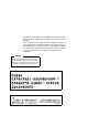
Miscellaneous Menu If a fault occurs while printing a hex dump, the printer reverts to the normal fault state. When the fault is cleared, the printer resumes printing the hex dump (either a partial line with a form feed, or nothing at all). Top-of-form remains unaffected. Figure 5. Sample Hex Dump To begin a hex dump, first place the printer offline and enable the Hex Dump Mode option from the control panel. Next, place the printer online. Finally, send data to the printer from the host computer.
Chapter 3 Printer Configuration Display Language Display Language allows you to select the language used for control panel messages and configuration printouts. The available choices are English, German, French, Italian, Spanish, or Dutch. The default setting is English. File System Overwrite Allows you to prevent files from being overwritten by disabling the overwrite function. View Files Displays the list of files in the file system. Pressing the DOWN key displays the file size.
Font Memory Menu Font Memory Menu Font Memory Max Char Memory 50 Kbytes 100 Kbytes 150 Kbytes . 300 kbytes* . 900 Kbytes Max Fonts Loaded Max Cache Memory Max Cache Size 50 Kbytes 100 Kbytes 150 Kbytes . 200 kbytes* . 900 Kbytes 50 characters 100 characters 150 characters . . . 900 characters* Font Weight Installed Fonts 1 font 2 fonts 3 fonts . . . 20 fonts Max Cached Char 1 Kbyte* 2 Kbytes 3 Kbytes . . . 20 Kbytes Lists all installed fonts Standard Chars. 10 11 12 . . 115* . .
Chapter 3 Printer Configuration NOTE: The Font Memory Menu is not available in the PCL5 emulation. For most applications, the default settings for font memory are acceptable. Therefore, do not change the defaults unless your application requires an uncommon font memory configuration. Activating Font Memory Options After selecting any of the “Font Memory” options, perform the following steps to activate the new value: 1. Save your configuration changes. See the Config.
Font Memory Menu Max Cache Memory The Maximum Cache Memory option specifies the size of the memory block that can be allocated to the font cache. The font cache stores bitmaps that are created on demand from the font outlines stored in Flash memory. The cache allows the printer to print scalable fonts at optimum speed.
Chapter 3 Printer Configuration The allowable range is 1 KBytes to 20 KBytes, in 1-KByte increments. The default value for this parameter is 1 KBytes. Max Fonts Loaded The Maximum Fonts Loaded option specifies the number of scalable font outlines that can be concurrently loaded into RAM in the printer. The allowable range is 1 to 20 fonts, in 1-font increments. The default value for this parameter is 5 fonts.
Test Print Menu Test Print Menu Test Print Test Pattern Lines* Grid Checkerboard No. of Pages 1 2 5 10 Continuous printout Start Test Press ENTER The Test print menu defines and activates a test printout. You must specify the test pattern and the number of pages to be printed. Test Pattern The Test Pattern option selects the type of pattern to be used for the test printout. You may select a Lines test pattern, a Grid test pattern, or a Checkerboard test pattern.
Chapter 3 Printer Configuration Print Statistics Menu Print Statistics System Memory Printer Life Power-up Time Printer Pages Level A Pages Level B Pages Level C Pages Level D Pages Level E Pages Level F Pages Level G Pages Level H Pages The Print Statistics menu provides access to information about memory capacity and printer usage. System Memory The L5000 series printers have 32 MB of RAM (Random Access Memory), and 8 MB of Flash Memory.
Maintenance Menu Maintenance Menu Maintenance User Maint. Tech Service Clear Level A Clear Level B Clear Level C Clear Level D Clear Level E Clear Level F Clear Level G Clear Level H The Maintenance menu provides access to information about service levels for end-users and service technicians. User Maint The User Maintenance option resets the service level page count after you complete preventive maintenance (levels A, B, and C). See Chapter 5, “Scheduled Maintenance,” for additional information.
Chapter 3 Printer Configuration Virtual Printer Menu Virtual Printer Virtual Printer LP+ Empty (or any other emulation currently loaded in the printer) The Virtual Printer menu allows the user to select which emulation they want to use that is currently loaded in flash memory. Virtual Printer The Virtual Printer option allows the user to select which emulation, or partition, the printer should switch to using. If the user selects Empty, the printer automatically enters download mode.
Loading Flash Memory (If Equipped) Loading Flash Memory (If Equipped) Printer emulation and operating system software are loaded into flash memory at the factory, but you will install software or files in the following situations: • The customer buys the PGL or VGL graphics, Expansion-CT, or IPDS option after the printer is installed • • • • • The customer needs to upgrade printer software The customer needs different emulation software You have replaced the controller board You have added or replaced
Chapter 3 The CNVT2FLS Utility Program The CNVT2FLS Utility Program The CNVT2FLS program is a DOS utility that is supplied with the flash software on diskette. This utility converts logo, form, TIFF, setup, and font files into downloadable format. To convert files into downloadable format, do the following: 1. Create a directory on the hard drive and copy the CNVT2FLS utility to that directory. 2. Copy all of the files to be converted to the directory where the CNVT2FLS utility resides. 3.
Loading Flash Memory (If Equipped) IMPORTANT • The first file name following the command name is the name of the input file that you want to convert. • The second file name is the name of the downloadable output file, which the utility will create. • The third file name is the name of the output file as it will be stored in the flash memory after downloading and later displayed on the printer LCD menus. • The “A” parameter in the command line is a fixed parameter that must always be entered.
Chapter 3 Downloading Into Flash Memory 7. To convert a setup file, enter the following at the DOS prompt, for example: CNVT2FLS setup.ptx setup.dwn setup.ptx A where setup.ptx is the name of one of the setup files you want to convert. This command converts the specified setup file, creating the downloadable file setup.dwn. 8. Repeat step 7 for any additional setup files to be converted. 9.
Loading Flash Memory (If Equipped) To download emulation software, as well as downloadable files for logos, forms, TIFF, setup, and fonts to the printer, do the following: 1. If you plan to download any logo, form, TIFF, setup, or font files into the printer, you must first use the supplied CNVT2FLS DOS utility program to convert these files into downloadable format. See page 110. (Emulation files require no conversion.) 2. Take the printer offline by pressing the ONLINE key. 3.
Chapter 3 Downloading Into Flash Memory 12. Connect the parallel data cable to the parallel port of the printer. 13. Plug the printer AC power plug into its electrical outlet. 14. Power on the computer. 15. Set the printer power switch to | (on). 16. If you have no emulation software to install and you are installing only logo, form, TIFF, setup, or font files, skip to step 43. If you do have emulation software to install, continue with step 17. 17.
Loading Flash Memory (If Equipped) The file name of the compressed file on the diskette takes the form part_num.zip, for example 123456.zip. 24. At the DOS prompt type: A:\PKUNZIP A:\part_num where part_num is the six digit number you noted in the previous step. (Replace A: with B: if you are using the B drive.) 25. The PKUNZIP program will execute, and the following message will appear on the computer screen: Insert disk #1 - Press a key when ready 26.
Chapter 3 Downloading Into Flash Memory 30. Type the following at the DOS prompt: DIR You will see a directory listing containing the file part_num.exe, where the filename is the six digit number (e.g., 123456.exe) you noted above. Write down the complete name of the file with the .exe extension. This is the file you will download into the printer. 31. Skip to step 35. 32. Insert the emulation diskette into diskette drive A (or B) of the computer. 33.
Loading Flash Memory (If Equipped) 37. At the DOS prompt on the computer type, for example: 123456.exe -pb where 123456.exe is the emulation file you noted in step 30 (for an emulation on multiple diskettes) or in step 34 (for an emulation on a single diskette). This command expands the emulation file, then copies it as a binary file into the flash memory in the printer. NOTE: If you are downloading the file using the LPT2 port on the computer, enter the following DOS command, for example: 123456.
Chapter 3 Downloading Into Flash Memory 45. On the printer control panel, press and hold down the ONLINE + PAGE EJECT keys. Without releasing the keys, power the printer on. Continue holding the ONLINE and PAGE EJECT keys down. 46. When you see “WAITING FOR FILE DOWNLOAD” on the LCD, release the ONLINE and PAGE EJECT keys. 47. If the software to be installed is already on the hard drive, change to the drive and directory where the software resides, then skip to step 50.
Loading Flash Memory (If Equipped) 51. Download the files to the printer by using the DOS copy command. You can download the files one at a time by entering one file name per DOS copy command. Alternatively, you can copy multiple files in one copy command. To download one file at a time, enter the following at the DOS prompt, for example: copy /b file_name.dwn LPT1 To download multiple files, enter the following at the DOS prompt, for example: copy /b file_name1.dwn+file_name2.dwn+...
Chapter 3 Downloading Into Flash Memory 60. Disconnect the parallel data cable from the computer and from the printer. 61. Reconnect the customer’s data input cable(s) to the printer, if required. 62. Plug the printer AC power plug into its electrical outlet. 63. Set the printer power switch to | (on). 64. Using the configuration printouts you made in step 3 and step 6, restore the printer configuration(s).
Flash Messages Flash Messages Table 2. Flash Messages Error Code Message Explanation H0 TEST HARDWARE PLEASE WAIT The printer is running its hardware self-test. H1 DIAGNOSTIC PASSED The self-test has finished, and there were no errors. H2 Waiting For File Download The system is now ready for the emulation or file download. H3 Loading File From Port xxx% The system is currently downloading the emulation or file. H4 Clear Flash Please Wait...
Chapter 3 Downloading Into Flash Memory Table 2. Flash Messages 122 K2 WRONG FILE CHECKSUM The printer detected emulation or file corruption during download or emulation bootup. Re-install the emulation or re-download the flash files. K3 DC PROGRAM NOT VALID There is no emulation installed or the emulation in flash memory is corrupted. Install/re-install emulation software to the printer. K4 NO FLASH FILE SYSTEM The flash file system is corrupted or the flash memory is unformatted.
4 Consumables Replacement Consumable Replacement Replacement Intervals For the best print quality, replace the printer consumables at the intervals specified below. The yield of the supplies is based on a 4% coverage of letter size (8.5 inch x 11 inch) paper. However, the yield may vary according to your print applications, environmental conditions, and toner density setting.
Chapter 4 Consumable Replacement Replacing The Toner Cartridge NOTE: When replacing the toner cartridge, put the old cartridge on a disposable wrapper (e.g., paper towels, newspaper) to minimize toner spillage. Vinyl gloves may be worn to prevent toner from contacting the skin. If necessary, use only cold water to remove toner from skin or clothing. Opening The Front Cover To replace the toner cartridge, perform the following steps: 1. Take the printer offline. 2.
Replacing The Toner Cartridge 3. Rotate the old toner cartridge counterclockwise until the notch is aligned with the pin in the toner hopper, and remove the cartridge. 3 1 2 Legend: 1) 2) 3) Toner Cartridge Positioning Pin Notch 4. Put the old cartridge into a plastic bag and discard it. 5. Keep the new toner cartridge in its package. Holding it level, shake it back and forth several times as shown by the arrows. This loosens the toner in the cartridge. 1 Legend: 1) Toner Cartridge 6.
Chapter 4 Consumable Replacement 7. With the cover tape facing up, begin inserting the cartridge into the toner hopper, and slowly pull off the cover tape in the direction of the arrow. Remove the last of the tape just as the cartridge is completely inside the hopper. 1 4 2 3 Legend: 1) 2) 3) 4) Toner Hopper Cover Tape Notch Pin 8. Fit the notch to the pin on the developing unit. Push the new toner cartridge as far as possible into the toner hopper.
Replacing The Toner Cartridge 9. Rotate the cartridge clockwise until it stops. 1 Legend: 1) Toner Cartridge 10. If any toner has spilled, remove it with wet tissue paper or a toner vacuum. 11. Close the front upper cover.
Chapter 4 Consumable Replacement Replacing The Waste Toner Bottle When the “WASTE TONER FULL” message appears on the control panel, replace the waste toner bottle by performing the following steps, and discard the full bottle. Do not reuse the bottle. To replace the waste toner bottle, perform the following steps: 1. When paper motion stops, wait 15 seconds, then open the printer front upper cover. (See page 124.) 2.
Replacing The Waste Toner Bottle 3. Remove the cap from the outside of the waste toner bottle, and cap the toner bottle. 1 2 Legend: 1) 2) Cap Waste Toner Bottle 4. Remove the waste toner bottle from the unit and discard it. 5. Install a new waste toner bottle. 6. Close the printer front cover. 7. Clear Error 28, “Waste Toner Full,” as follows: a. Press CLEAR. b. Unlock the configuration menu by pressing the UP + DOWN keys at the same time. c.
Chapter 4 Consumable Replacement Installing The Photoreceptor Drum Drum life depends on media used and proper maintenance and operation of the printer. Print media other than bond paper (e.g., labels, card stock, plastic, or vinyl) can reduce drum life as much as 50%. To replace the drum, you need a drum auxiliary rod and a flat-tip screwdriver. Please read all steps before beginning the replacement procedure. CAUTION Do not do this procedure unless you have received the appropriate training.
Installing The Photoreceptor Drum 4. Remove the three thumbscrews on the upper inner cover. Then remove the cover. 1 2 Legend: 1) 2) CAUTION Upper Inner Cover Thumbscrews (3) Failure to perform Step 5 will damage the photoreceptor drum. 5. Rotate the developing unit lever fully clockwise so that it is pointing straight up (to separate the developing unit from the photoreceptor drum).
Chapter 4 Consumable Replacement 6. Remove the developing unit by holding the lever in one hand and pulling the developing unit partially out of the printer. 1 Legend: 1) Hanger 7. With the other hand, grasp the hanger and remove the developing unit from the printer. 8. Vacuum any spilled toner.
Installing The Photoreceptor Drum CAUTION The transfer charger must be in the down position to avoid scratching the drum. Failure to perform steps 9 and 10 will damage the drum. 9. Rotate the transfer elevator drive shaft counterclockwise. Watch the charger movement: a. If the charger starts to move up, it is already in the down position. b. If the charger starts to move down, continue to rotate the drive shaft until the charger reaches the complete down position.
Chapter 4 Consumable Replacement 10. Lower the transport unit by turning the green lever on the transport unit to the left.
Installing The Photoreceptor Drum 11. Loosen the three thumbscrews securing the drum plate and remove the drum plate. 1 2 4 3 Legend: 1) 2) 3) 4) Drum Plate Thumbscrews (3) Screws (2) Lower Inner Cover 12. Remove the two screws on the lower inner cover. Then remove the cover.
Chapter 4 Consumable Replacement 13. Remove the nut from the end of the drum shaft. 1 Legend: 1) Nut 14. Screw the drum auxiliary rod onto the drum shaft.
Installing The Photoreceptor Drum CAUTION Avoid touching the surface of the drum with your hands, which reduces the life of the drum. 15. Carefully pull the old drum outward along the drum auxiliary rod. Hold the front and back ends when the drum is nearly out of the printer, and remove it with both hands. 1 Legend: 1) Drum 16. Pack the old drum for shipment using the original packaging material, and close the cover of the box. 17. Wipe the drum shaft clean with a cloth.
Chapter 4 Consumable Replacement 19. Using both hands, carefully slide the drum onto the drum auxiliary rod. When the drum reaches the area where the auxiliary rod connects to the drum shaft, lift the drum very slightly over the connection. Then let the drum rest on the rubber rollers as you gently guide it into the printer. CAUTION The drum must rest on the rubber rollers to avoid being scratched. 20.
Proper Disposal Of A Drum Unit 26. Install the developing unit.(See page 140.) 27. Raise the transport unit by reversing step 10. 28. Install the upper inner cover and tighten the thumbscrews. 29. Close the waste toner recovery unit and ensure that it latches. 30. Close the printer front cover. Proper Disposal Of A Drum Unit Due to the nature of the material used in drum manufacturing, federal regulations prohibit inappropriate disposal of laser print drums.
Chapter 4 Consumable Replacement Developing Unit Installation CAUTION Failure to perform step 1 will damage the photoreceptor drum. 1. On the developing unit, rotate the lever fully clockwise so that it is pointing straight up. 1 2 3 Legend: 1) 2) 3) Guide Rail Hanger Lever 2. Holding the lever in one hand and the hanger in the other hand, insert the developing unit on the guide rail.
Developing Unit Installation 3. Rotate the hanger to the right so that it rests against the developing unit, and push the developing unit in. 4. Rotate the developing roller knob counterclockwise until the unit drops into its final resting position. The positioning pin should protrude through the main body of the developing unit.
Chapter 4 Consumable Replacement 5. Rotate the developing unit lever fully counterclockwise to lock the developing unit in place. 6. Install the upper inner cover, and secure it with the three thumbscrews. 1 2 2 Legend: 1) 2) Upper Inner Cover Thumbscrews (3) 7. Close the waste toner recovery unit and ensure that it latches. 8. Close the printer front cover.
Replacing The Developer Replacing The Developer 10 1 9 Cross Section of Developing Unit 2 8 7 3 4 6 4 5 Legend: 1) 2) 3) 4) 5) 6) 7) 8) 9) 10) Toner Cartridge Toner Hopper Auger Toner Sensor Developing Tank Developing Roller Toner Supply Roller Screws Cover Developing Unit 143
Chapter 4 IMPORTANT Consumable Replacement When replacing developer in an existing developing unit, you must empty and clean the unit before adding new developer (every 150,000 pages). Developing Unit Removal 1. Turn the power switch OFF. 2. Prepare a plastic bag in which the developing unit can be placed. 3. Remove the developing unit from the printer. (See page 147.) 4. Place the developing unit in the plastic bag. 5.
Developing Unit Removal 6. Remove the three screws on the developing unit cover and remove the cover. 1 Legend: 1) CAUTION Toner Spray-Guard Brush The toner sensor is sensitive to both electrostatic discharge (ESD) and positional adjustment. Do not touch the sensor with your hand or jar it from its factory-set position. 7. With the developing unit held in the plastic bag, do the following: a.
Chapter 4 Consumable Replacement 10. Vacuum the toner from the toner spray-guard brush on the developing unit. 11. Shake the new developer bottle several times, remove the bottle cap, and screw the nozzle tightly onto the bottle. 12. While rotating the developing roller knob counterclockwise, evenly pour the entire bottle of developer powder into the developing unit. 1 2 Legend: 1) 2) Developer Bottle Developing Roller Knob 13. Replace the cover and tighten the screws.
Replacing The Developing Unit Replacing The Developing Unit CAUTION Do not do this procedure unless you have received the appropriate training. Do not damage the sensors while cleaning the developing unit. (If damage occurs, contact your service representative.) Developing Unit Removal 1. Turn the power switch OFF. 2. Open the printer front upper cover. (See page 124.) 3. Open the waste toner recovery unit by pushing downward on the opening lever.
Chapter 4 Consumable Replacement 4. Remove the three thumbscrews and the upper inner cover.
Replacing The Developing Unit CAUTION Failure to perform step 5 will damage the photoreceptor drum. 5. Rotate the developing unit lever fully clockwise so that it is pointing straight up (to separate the developing unit from the photoreceptor drum). 1 Legend: 1) Lever 6. Remove the developing unit by holding the lever in one hand and pulling the developing unit partially out of the printer.
Chapter 4 Consumable Replacement 7. With your other hand, grasp the hanger and remove the developing unit from the printer. 1 Legend: 1) Hanger 8. Place the old developing unit in a plastic bag and dispose of it properly. 9. Vacuum any spilled toner. 10. Remove a new developing unit from its package, and add developer to the unit.
5 Scheduled Maintenance Maintaining Print Quality To maintain good print quality, clean the printer according to the schedules and procedures listed in this chapter. 1. Do a General Cleaning. (See page 164.) 2. Clean the main charger, precharger, and transfer charger. For cleaning instructions, see page 172 for the main charger, and page 177 for the precharger and transfer charger. 3. If print quality problems occur, clean the following areas (see page 152 for tool part numbers): a.
Chapter 5 Maintenance Tools Maintenance Tools In order to perform maintenance on the printer, you need the following tools: Item Part Number Brush Cleaner 703531-169 Drum Auxiliary Rod 703531-170 Drum Freshener Pad 703531-171 Fuser Cover Glass Scraper 703531-187 Special Dry Tissue Paper 703531-188 Standard Toner Vacuum Cleaner See recommended models below Toraysee Cloth 703531-183 Wire Cleaner 703531-168 9 inch Phillips Screwdriver #1 N/A Recommended toner vacuum cleaner models are: •
Service Level Page Counts IMPORTANT Keep a record of all maintenance done on your printer. Maintenance log sheets are provided in Appendix A. Photocopy the pages and keep your maintenance log in a binder near the printer. Every time you or your service provider do printer maintenance make an entry in the log. Each time you complete a level of preventive maintenance, you must reset the service level page count by selecting the User Maintenance option on the Maintenance menu. (See page 107.
Chapter 5 Clearing Service Level Messages A service level includes all levels precede it. For example, at 150,000 pages, you should do Level B and Level A service. At 900,000 pages, your service provider must do Level F, Level E, and Level D service. Note that this condition will not cause the printer to stop printing. When one of the above messages appears, do the appropriate scheduled maintenance or call your factory-trained service representative to do the maintenance.
User Cleaning Schedule Maintenance Schedules User Cleaning Schedule Each time you perform maintenance, you must reset the service level page count by selecting the User Maintenance option on the Maintenance menu. (The Maintenance menu is detailed in Chapter 3, “Printer Configuration.”) This removes the maintenance error message. Do the actions in Table 4 after the specified number of letter size pages (4% coverage) have been printed.
Chapter 5 Maintenance Schedules User Replacement Schedule Replace the following items after the specified number of letter size pages (4% coverage) have printed. Appendix A, “Maintenance Log Sheets,” contains log sheets you can photocopy. Table 4.
Tech Service Replacement Schedule Tech Service Replacement Schedule Use the following maintenance kits to replace the listed printer components after the specified number of letter size pages (4% coverage) have been printed. Appendix A, “Maintenance Log Sheets,” contains log sheets you can photocopy for your use.
Chapter 5 Maintenance Schedules Item Maintenance Kit, Level E, L5035 • • • • • • • • 158 Main charger Precharger Transfer charger Smoke filter Cleaning unit Halogen lamp Transport belt (set of 3) Cutter motor Part Number 706803-001
Tech Service Replacement Schedule Maintenance Kit, Level F, L5035 • • • • • 706809-001 Main charger Precharger Transfer charger Smoke filter Xenon (flash) lamp 159
Chapter 5 Maintenance Schedules Item Maintenance Kit, Level G, L5035 • • • • • • • • • 160 Main charger Precharger Transfer charger Smoke filter Cleaning unit Halogen lamp Transport belt (set of 3) Cutter motor Trigger coil unit Part Number 706815-001
Tech Service Replacement Schedule Item Maintenance Kit, Level H, L5035 • • • • • • • • • • • • • • • • • • • • • Part Number 706827-001 Main charger Precharger Transfer charger Smoke filter Cleaning unit Halogen lamp Transport belt (set of 3) Cutter motor Trigger coil unit Capacitor Belt (60S3M264, set of 2) Sleeve motor unit Magroll motor unit Lamp housing filter EPS1 EPS3 EPS4 Capacitor Discharge LEDs (PEL) LED air filter L5035 Brush kit 161
Chapter 5 Maintenance Schedules Table 5.
Tech Service Replacement Schedule Table 5. Parts The Service Provider Replaces Item Part # Frequency (Pages) Action Service Level Feed Roller 703531-563 2,400,000 See Note 2 Clean and inspect; replace if worn. H Resist Roller 703531-565 2,400,000 See Note 2 Clean and inspect; replace if worn H Roller, Pre Drum 703531-590 2,400,000 See Note 2 Clean and inspect; replace if worn.
Chapter 5 General Cleaning AVISO El condensador flash del fusor se debe sustituir como mínimo cada 2.400.000 páginas de tamaño carta. De lo contrario, pueden causarse daños a los equipos y al personal. ATTENTION Pour éviter tout risque de dégâs matériels et corporels, remplacez l’unité de flashage aprés l’impression de 2 400 000 pages de format lettre. AVVERTENZA Il condensatore dell’unitá fusore deve essere sostituito almeno ogni 2.400.000 pagine in fprmato lettera.
Cleaning Following is the general cleaning procedure: 1. Turn the power switch OFF. 2. Open the printer front upper cover. (See page 124.) 3. Inside the front cover, vacuum up the toner, paper dust, etc. 4. On the waste toner recovery unit, press the Open lever down. Pull the handle toward you and open the unit.
Chapter 5 General Cleaning 5. Vacuum the developing unit and toner hopper. 6. Vacuum the cleaning unit.
Cleaning 7. Vacuum the fuser unit. 8. Vacuum the lamp housing filter on the underside of the fuser unit.
Chapter 5 CAUTION General Cleaning The transfer charger must be in the down position to avoid scratching the drum. Failure to perform steps 9 and 10 will damage the drum. 9. Rotate the transfer elevator drive shaft counterclockwise. Watch the charger movement: a. If the charger starts to move up, it is already in the down position. b. If the charger starts to move down, continue to rotate the drive shaft until the charger reaches the complete down position.
Cleaning 12. Using a vacuum, clean the toner, paper dust, etc. Be sure to clean under the transport unit as well. 13. Wipe off the dirt on the transport surface with wet tissue paper. 14. Using an ammonia-based wax-free cleaner or rubbing alcohol, clean the belts to remove residue buildup and restore their tacky surface. 15. After cleaning, return the transport unit to its original position (push it into the printer while holding down the green lever).
Chapter 5 General Cleaning 16. Using a vacuum, clean the toner, paper dust, etc. in the tractor area. 1 Legend: 1) Tractor 17. Open the paper guide by pressing the green lever down.
Cleaning 18. Open the lid on the top cover. 19. Open the paper guide by pressing the guide lever down. 20. Using a vacuum, clean the paper dust, etc. inside the paper guide.
Chapter 5 General Cleaning Cleaning The Chargers 1. Turn the power switch OFF. 2. Open the printer front upper cover. (see page 124) 3. Loosen the thumbscrew and remove the main charger by pulling it toward you. 1 2 Legend: 1) 2) Thumbscrew Main Charger 4. Place the main charger on a flat, clean work surface.
Cleaning The Chargers CAUTION Use caution in handling to avoid damaging or breaking the charger wires. 5. Using the brush cleaner (listed on page 152), clean the exposed side of the charger grid and the body of the main charger to remove paper dust, etc., as shown below.
Chapter 5 General Cleaning 6. Position the main charger with the charger grid up and the front end of the charger toward you, as shown in the figure below. Refer to the figure below and the inset drawing in the figure, and remove the charger grid from the main charger as follows: a. While pressing the front retaining tab toward the rear of the charger, unhook the rear end of the charger grid from the rear retaining tab. b. Release the front retaining tab, then remove the charger grid from it.
Cleaning The Chargers 7. Using the brush cleaner, clean both sides of the charger grid, as shown below. 1 2 Legend: 1) 2) Brush Cleaner Charger Grid 8. Using the wire cleaner (listed on page 152), clean the two wires in the main charger, as shown below. Clean both wires thoroughly. When dirt is caked on, the wires feel gritty. When clean, the wires feel smooth.
Chapter 5 General Cleaning 9. Install the charger grid. 10. Return the main charger to its original position. Fasten the main charger screw to secure it. 11. Open the waste toner recovery unit.
Cleaning The Chargers 12. Loosen the thumbscrews (2), precharger screw and transfer/ separator charger screw, and remove the chargers by pulling them toward you. 1 3 2 Legend: 1) 2) 3) Thumbscrews Transfer/Separator Charger Precharger 13. Place the chargers on a flat, clean work surface.
Chapter 5 CAUTION General Cleaning Use caution in handling to avoid damaging or breaking the charger wires. 14. Using the brush cleaner and the wire cleaner, clean the chargers by removing the dust and dirt on the wires. (The precharger contains one wire, while the transfer/separator charger contains two wires). 15. After cleaning, return the chargers to their original positions. Fasten the charger screws to secure them.
Cleaning The Fuser Unit Cover Glass CAUTION The transfer charger must be in the down position to avoid scratching the drum. Failure to perform steps 3 and 4 will damage the drum. 3. Rotate the transfer elevator drive shaft counterclockwise. Watch the charger movement: a. If the charger starts to move up, it is already in the down position. b. If the charger starts to move down, continue to rotate the drive shaft until the charger reaches the complete down position.
Chapter 5 General Cleaning 4. Lower the transport unit by turning the green lever on the transport unit to the left. 5 1 2 4 3 Legend: 1) 2) 3) 4) 5) Holding Plate Thumbscrew Green Lever Fuser Unit Thumbscrew (2 places not visible) 5. Loosen the thumbscrews on the right and left fuser unit holding plates. 6. Grasp the handle and pull out the fuser unit until the second handle is visible. 7. Grasp the second handle with your other hand and remove the fuser from the printer. 8.
Cleaning The Fuser Unit Cover Glass CAUTION Do not scratch or place your hands directly on the cover glass. Fingerprints on the cover glass or lamps will cause them to break. 9. Using the fuser cover glass scraper (listed on page 152), remove the dirt and toner buildup on the cover glass surface. 1 Legend: 1) Scraper 10. Wipe away any remaining toner or dirt with a Toraysee cloth (listed on page 152).
Chapter 5 General Cleaning 11. Remove the two screws that secure the lamp duct filter unit to the fuser, then remove the lamp duct filter unit and the foam gasket. 1 2 3 4 5 Legend: 1) 2) 3) 4) 5) Foam Gasket Screw (4) Filter Holding Plate Lamp Filter (Air Filter) Lamp Duct Filter Unit 12. Remove the two screws that secure the filter holding plate to the lamp duct filter unit, then remove the lamp filter. 13. Vacuum the lamp filter, then reinstall it. 14. Vacuum any paper dust from the printer frame.
Cleaning The Cut Sheet Option Rollers Cleaning The Cut Sheet Option Rollers NOTE: This procedure only applies to printers with the cut sheet option installed. 1. Turn the power switch OFF. 2. Remove the upper and lower paper cassettes from the printer.
Chapter 5 General Cleaning 3. There are two pickup roller units (upper and lower) located at the back of the cassette opening. On the upper roller unit, loosen the green thumb screw. Slide the unit to the left, and pull the unit toward you and out of the printer. 1 Legend: 1) Green Thumbscrew 4. On the lower roller unit, loosen the green thumb screw. Slide the unit to the left, and pull the unit toward you and out of the printer. 5.
Cleaning The Cut Sheet Option Rollers 6. Install the upper and lower pickup roller units: a. Align the shaft pin with the slot in the coupling, and align the alignment pin on the unit with the hole in the frame. b. Tighten the green thumb screw.
Chapter 5 General Cleaning 7. There are two reverse roller units (upper and lower) located at the back of the cassette opening (underneath the upper and lower pickup roller units). On the upper reverse roller unit, loosen the green thumb screw. Remove the roller unit by moving it downward while sliding it to the left.
Cleaning The Cut Sheet Option Rollers 8. On the lower reverse roller unit, loosen the green thumb screw. Remove the roller unit by moving it downward while sliding it to the left. 1 Legend: 1) Thumbscrews 9. Wipe off the dirt on the reverse rollers with a Toraysee cloth (listed on page 152). Remove any label adhesive or forms residue with rubbing alcohol.
Chapter 5 General Cleaning 10. Install the upper and lower reverse roller units: a. Align the shaft pin with the slot in the coupling, and align the alignment pin on the unit with the hole in the frame. b. Tighten the green thumb screw. 1 4 2 3 Legend: 1) 2) 3) 4) Hole in Frame Shaft Pin Alignment Pin Coupling 11. Install the upper and lower paper cassettes into the printer.
Cleaning Major Cleaning Cleaning 1. Turn the power switch OFF. 2. Open the printer front upper cover. (See page 124.) 3. Open the waste toner recovery unit by pushing downward on the lever. Pull the green handle and swing the unit outward away from the printer.
Chapter 5 Major Cleaning 4. Remove three thumbscrews on the upper inner cover. Then remove the cover.
Cleaning 5. Loosen the three thumbscrews securing the drum plate and remove the drum plate. CAUTION Do not turn the cleaning unit upside down, or toner might spill. Do not touch the brush surface with your hand. 1 3 2 Legend: 1) 2) 3) Thumbscrews (3) Drum Plate Cleaning Unit Handle 6. Remove the cleaning unit by grasping its handle and pulling it toward you.
Chapter 5 Major Cleaning 7. Vacuum the brush on the cleaning unit. Turn the end of the shaft to rotate the brush. Continue to rotate and vacuum the brush until the entire brush surface is clean. .
Discharge LED Discharge LED CAUTION Do not flex the discharge LED as it will break. 8. Remove the discharge LED retaining screw. 9. Remove the discharge LED by pulling it toward you. 1 2 Legend: 1) 2) Discharge LED Screw 10. Using a Toraysee cloth (listed on page 152), wipe off the dirt on the discharge LED.
Chapter 5 Major Cleaning Photoreceptor Drum 11. Install the discharge LED. 12. Remove the developing unit. (See page 147.) 13. Remove the photoreceptor drum. (See page 130). 14. Place the photoreceptor drum on a covered work surface. 15. If the drum is only slightly dirty, clean it with ethanol or isopropyl alcohol. Do not use acetone. CAUTION When cleaning the photoreceptor drum, note the following: • • Do not touch the drum surface with your hands. • Cleaning the drum may result in stains.
SELFOC Lens® (LED Print Head) 19. To avoid exposing the drum to light for a prolonged period of time, temporarily pack the drum in its original packaging material, and close the box cover. Set the drum aside for now. (It will be installed in a later step.) 20. Remove the drum auxiliary rod from the drum shaft. 21. Wipe the drum shaft clean with a cloth. SELFOC Lens® (LED Print Head) 22. Loosen the thumb screw and remove the main charger by pulling it toward you.
Chapter 5 Major Cleaning 24. Wipe the SELFOC lens by moving a Toraysee cloth from the inner part of the printer toward you. Wipe the lens in this manner several times until there is no more dirt on the cloth. NOTE: Always wipe the SELFOC lens with the unused side of the Toraysee. 2 1 Legend: 1) 2) SELFOC Lens Drum Surface Potential Sensor 25. Install the main charger. 26. Install the photoreceptor drum. (See page 130.) 27. Install the developing unit. (See page 147.) 28. Install the cleaning unit.
6 Troubleshooting Troubleshooting This chapter discusses diagnostic tests, paper jams, and system messages (status and error). Diagnostics The printer includes self-diagnostic circuits and software to aid in the discovery, prevention, and correction of system problems and failures. There are two kinds of diagnostics: offline and online. Offline Diagnostics Most of the software diagnostics are executed when the printer is powered on, and when you request diagnostic information through the control panel.
Chapter 6 Fanfold Paper Jams • Print Configuration: Prints all current configuration parameters in the printer, including Print Statistics (Config. Control menu). Online Diagnostics When online, the printer continues to sense and report problems or conditions as they arise. When an error is detected, the printer halts, lights the appropriate LED, and displays the proper error message on the control panel. The error message will remain displayed until the error condition is cleared and you press CLEAR.
Paper Jam Near The Paper Output Section Paper Jam Near The Paper Output Section 1. When paper motion stops, wait 15 seconds, then open the front cover. (See page 124). 2. Push down on the opening lever of the waste toner recovery unit, and pull the green handle to swing the unit outward.
Chapter 6 CAUTION Fanfold Paper Jams The transfer charger must be in the down position to avoid scratching the drum 3. Rotate the transfer elevator drive shaft counterclockwise. Watch the charger movement: a. If the charger starts to move up, it is already in the down position. b. If the charger starts to move down, continue to rotate the drive shaft until the charger reaches the fully down position.
Paper Jam Near The Paper Output Section CAUTION To avoid damaging the printer or causing false paper jams, the transport lever must be in the fully down position before opening the transport unit. 4. Lower the transport unit by turning the green lever on the transport unit to the left. 1 Legend: 1) Green Lever 5. Check to see if any paper is jammed. 6. To raise the scuff roller holding the paper, turn knob C clockwise 90° as shown below.
Chapter 6 Fanfold Paper Jams 7. Separate the paper at the perforations on both the paper input and the output sections. Then pull the jammed paper out. When removing the paper from the paper input section, raise the tractor gates first, then pull out the jammed paper.
Paper Jam At The Back Of The Paper Cassette CAUTION To avoid damaging the printer or causing false paper jams, the transport lever must be in the fully down position before closing the transport unit. 8. After removing the pieces of jammed paper, restore the transport unit, waste toner recovery unit, and knob C to their original positions, and close the front cover. 9. Reload the paper. Cut Sheet Paper Jams Paper Jam At The Back Of The Paper Cassette 1. Pull out the paper cassette.
Chapter 6 Cut Sheet Paper Jams 2. To lower the paper guide, pull the green lever up. Remove any jammed paper, and return the green lever to its original position.
Paper Jam At The Back Of The Paper Cassette 3. Open the lid on the top cover, and pull the green lever up. Remove any jammed paper, and return the green lever to its original position.
Chapter 6 Cut Sheet Paper Jams Paper Jam In The Transport Input Section 1. When paper motion stops, wait 15 seconds, then open the front cover. (See page 124.) 2. Open the waste toner recovery unit cover, and swing out the unit.
Paper Jam In The Transport Input Section CAUTION The transfer charger must be in the down position to avoid scratching the drum 3. Rotate the transfer elevator drive shaft counterclockwise. Watch the charger movement: a. If the charger starts to move up, it is already in the down position. b. If the charger starts to move down, continue to rotate the drive shaft until the charger reaches the fully down position.
Chapter 6 CAUTION Cut Sheet Paper Jams To avoid damaging the printer or causing false paper jams, the transport lever must be in the fully down position before opening or closing the transport unit. 4. To lower the transport route surface, turn the green transport unit lever to the left.
Paper Jam In The Transport Input Section 5. Remove knob A from its place as shown below. Attach knob A to the paper feed shaft, and turn knob A counterclockwise. This causes the jammed paper to be moved to the eject side. Remove any jammed paper, and return knob A to its original position. 1 2 Legend: 1) 2) Original Position of Knob A Knob A 6. Restore the transport unit and the waste toner recovery unit to their original positions, and close the front cover.
Chapter 6 Cut Sheet Paper Jams Paper Jam In The Transport Output Section 1. When paper motion stops, wait 15 seconds, then open the front cover. (See page 124.) 2. Pull up the bottom lever to raise the paper guide, and turn the green knob B counterclockwise. This moves the jammed paper to be removed to the paper feed section. Remove any jammed paper. 1 2 Legend: 1) 2) Knob B Bottom Lever (#1) 3. Lower the paper guide by restoring the bottom lever to its original position. Close the front cover.
Paper Jam In The Transport Output Section Paper Jam In The Face Up Or Down Paper Path 1. When paper motion stops, wait 15 seconds, then open the front cover. (See page 124.) 2. Push the top and middle levers down. Pull the bottom lever up to raise the paper guide. Turn the green knob C clockwise, and remove any jammed paper. (Levers are numbered on a label inside the printer, as shown below.) 4 3 1 2 Legend: 1) 2) 3) 4) Knob C Bottom Lever (#1) Middle Lever (#2) Top Lever (#3) 3.
Chapter 6 System Status And Error Messages System Status And Error Messages Messages When an error occurs, the printer displays an appropriate message on the control panel LCD. Some errors are operator-correctable, some require field service, and others require the print job be run again. Operator-correctable errors include paper jams, missing consumables, and power paper stacker problems.
Messages • Any pages left in the printer at the time of failure will be reprinted. No data is lost. • Fanfold paper: the printer reprints all pages that have not completely exited the printer at the time of failure. The exact number of pages that are reprinted is determined by the length of the page and where within the page the fault occurred. • Cut sheet paper: the printer determines how many pages did not exit the printer, and reprints all pages that did not exit.
Chapter 6 System Status And Error Messages Standby ... Clearing Fault • If the fault is not cleared: a. The printer beeps and briefly displays the following message: Faults Not Cleared b. The printer then redisplays the original fault message, or any other uncleared fault message. c. • Attempt to clear the fault condition again, or contact your service representative. If the fault is cleared, and if you do not need to reload the paper into the tractors (for example, the printer ran out of toner): a.
Messages Not Reprinting Failed Pages 5. Press ONLINE to resume printing. Note that pages have been lost. IMPORTANT If Reprint on Fault is disabled and an error occurs, and if either the “Reload Paper in Tractors” or “Not Reprinting Failed Pages” message appears, then any pages removed from the printer will not be reprinted, and the data on them will be lost. Procedure for Fault Clearing-Reprint on Fault Enabled 1. A fault occurs. 2. Clear the fault condition. 3. Press CLEAR. 4.
Chapter 6 System Status And Error Messages a. The printer goes OFFLINE. b. Press ONLINE to resume printing. • If the fault is cleared, and if you need to reload paper into the tractors (such as after a paper jam), the following message appears: Clear Paper Path for Reprint a. Reload the paper onto the tractors. b. Press CLEAR. The printer reprints only the pages affected by the fault (even though the message display reads “OFFLINE”). c. • Press ONLINE to resume printing.
Error Messages Error Messages Table 6, “Error Messages,” on page 218, lists errors by error code and shows which are operator-correctable, which require field service, and which require reprinting. • Operator-correctable errors include paper jams, missing consumables, and power paper stacker problems. • Errors requiring field service are printer failures that require the attention of service personnel.
Chapter 6 System Status And Error Messages Table 6.
Error Messages Table 6.
Chapter 6 System Status And Error Messages Table 6.
Error Messages Table 6. Error Messages Error Code Error Message Operator Correctable Field Service Required Reprint Required 44 Engine CPU Fail á 45 Engine CPU Fail á 46 Engine CPU Fail á 47 Engine CPU Fail á 48 Controller Comm. Fail á 49 Controller Comm. Fail á 4A Controller Comm. Fail á 4B Controller Comm. Fail á 4C Controller Comm. Fail á 4D Controller Comm.
Chapter 6 System Status And Error Messages Table 6. Error Messages Error Code 222 Error Message Operator Correctable Field Service Required Reprint Required 5B Stacker Fail á á 5C Stacker Fail á á 5D Stacker Comm. Fail 5E Reserved 5F Reserved 60 Cut-sheet Comm. Fail á 61 Cut-sheet Comm. Fail á 62 Cut-sheet Comm.
Error Messages Table 6.
Chapter 6 System Status And Error Messages TABLE NOTES: 1. For any error with Reprint on Fault enabled: If the printer stops while in the middle of printing a page, reloading the paper and reprinting are required. There may be other cases requiring reloading and reprinting; if so, a message will appear. 2. For any error with Reprint on Fault disabled: If the printer stops while in the middle of printing a page, reloading the paper is required and pages are lost. 3.
A Maintenance Log Sheets The log sheets on the following pages are intended for your use. These may be photocopied and kept in a binder near the printer. Be sure to use them each time either you or your service provider perform printer maintenance.
Appendix A Level A Maintenance - 15,000 Pages (User) Action Item Part # Clean General cleaning N/A Clean Main charger 705741-001 Clean Precharger 705742-001 Clean Transfer charger 705743-001 Clean See Note 1 Cover glass N/A Clean See Note 2 Cut sheet cassette pickup rollers 703531-050 Clean See Note 2 Cut sheet cassette reverse rollers 703531-051 Replace See Note 3 Toner cartridge 703532-001 Performed By Date Note 1: Every 15,000 pages or 6 paper jams, whichever occurs first.
Level B Maintenance -150,000 (User) Level B Maintenance -150,000 (User) Action Item Part # Clean General cleaning N/A Clean Main charger 705741-001 Clean Precharger 705742-001 Clean Transfer charger 705743-001 Clean See Note 1 Cover glass N/A Clean SELFOC lens N/A Vacuum Lamp housing filter 202838-001 Vacuum Cleaning unit 705740-001 See Note 2 Photoreceptor drum 703535-001 Replace See Note 3 Toner cartridge 703532-001 Replace Developer 703548-001 Replace Waste toner bot
Appendix A Level C Maintenance - 600,000 (User) Action Item Part # Clean General cleaning N/A Clean See Note 1 Cover glass N/A Clean SELFOC lens N/A See Note 2 Photoreceptor drum 703535-001 Replace Developing Unit 705739-001 Replace See Note 3 Toner cartridge 703532-001 Replace Waste toner bottle 703539-001 Clean See Note 4 Cut sheet cassette pickup rollers 703531-050 Clean See Note 4 Cut sheet cassette reverse rollers 703531-051 Performed By Date Note 1: Every 15,000 pages
Level D Maintenance - 300,000 (Service Kit) Level D Maintenance - 300,000 (Service Kit) Item Maintenance Kit, Level D, L5035 • • • • Part Number 706802-001 Main charger Precharger Transfer charger Smoke filter 229
Appendix A Level E Maintenance - 600,000 (Service Kit) Item Maintenance Kit, Level E, L5035 • • • • • • • • 230 Main charger Precharger Transfer charger Smoke filter Cleaning unit Halogen lamp Transport belt (set of 3) Cutter motor Part Number 706803-001
Level F Maintenance - 900,000 (Service Kit) Level F Maintenance - 900,000 (Service Kit) Maintenance Kit, Level F, L5035 • • • • • 706809-001 Main charger Precharger Transfer charger Smoke filter Xenon (flash) lamp 231
Appendix A Level G Maintenance - 1,200,000 (Service Kit) Item Maintenance Kit, Level G, L5035 • • • • • • • • • 232 Main charger Precharger Transfer charger Smoke filter Cleaning unit Halogen lamp Transport belt (set of 3) Cutter motor Trigger coil unit Part Number 706815-001
Level H Maintenance - 2,400,000 (Service Kit) Level H Maintenance - 2,400,000 (Service Kit) Item Maintenance Kit, Level H, L5035 • • • • • • • • • • • • • • • • • • • • • Part Number 706827-001 Main charger Precharger Transfer charger Smoke filter Cleaning unit Halogen lamp Transport belt (set of 3) Cutter motor Trigger coil unit Capacitor Belt (60S3M264, set of 2) Sleeve motor unit Magroll motor unit Lamp housing filter EPS1 EPS3 EPS4 Capacitor Discharge LEDs (PEL) LED air filter L5035 Brush kit 233
Appendix A 234
B Specifications Paper Specifications Paper types Fanfold (standard) Cut sheet (optional) Paper Sizes Cut sheet paper Fanfold paper Width Length* Letter (landscape), legal (portrait), ledger (portrait), A3 (portrait), B4 (portrait), A4 (landscape) 7 to 16 inches 1 to 30 inches, in multiples of 1/6 inch, (With optional power paper stacker, the length must be 7 to 12 inches, in multiples of 1/6 inch.) *Measured from main folding/cutting perforation to main folding/ cutting perforation.
Appendix B Dimension in Figure Specification Inch Millimeter Pin hole center to folding perforation 1/6, 1/4, 1/3, or 1/2 4.23, 6.35, 8.47, 1.20 8 Hole center line to edge of form 0.236 ±0.028 6.0 ±0.1 1 Hole diameter 0.156 ±0.004 4.0 ±0.1 N/A Distance between centers of two consecutive holes 0.500 ±0.002 12.7 ±0.05 5 Max. deviation of holes from their center line 0.004 0.1 6 Max. deviation Left Hand hole to companion Right Hand hole (Center Line to Center Line) 0.006 0.
Paper Specifications 2 1 1 3 9 4 8 7 5 6 6 Legend: 1) 2) 3) 4) 5) 6) 7) 8) 9) “B” Center Line Main Folding/Cutting Perforation “E” “C” “D” - Center Line Deviation Tractor Pin Hole “A” Fanfold Paper Paper thickness 0.
Appendix B Paper Weights Fanfold paper Cut sheet paper Paper feed Fanfold paper Cut sheet paper 18 to 44 lb. bond, 44 to 125 lb. tag/label 18 to 44 lb. bond Automatic paper parking mechanism incorporated 3000 sheets (18 lb.) 250 to 500 sheets (18 lb.) Paper Output Fanfold paper Cut sheet paper 2000 sheets into power stacker (18 lb.) (Maximum stack is 9.3 inches high.
Performance Characteristics Printing Speed Fanfold paper Paper Size Orientation 5.0 inches per second for continuous, fanfold forms. See the following table for printing speeds for common paper sizes Printing Speed (Pages per Minute) A4 Landscape 35 Letter Landscape 35 A4 Portrait 27 Letter Portrait 27 Cut sheet paper See the table below.
Appendix B Maximum effective print width Duty cycle 14.7 inches 300,000 total pages/month of fanfold paper form (11-inch length) and or cut sheet paper (letter) Mechanical life 5 years or 18,000,000 pages (11-inch length) 150 sec. max. 25 sec. max. 8,000 hrs./2,880,000 pages (letter size) 25% print to power on ratio 2 hour max.
Host Interfaces Host Interfaces NOTE: For interface details, see Appendix C, “Host I/O Interfaces.” Standard Centronics parallel, Dataproducts parallel, serial RS-232/422, IEEE 1284 parallel. NOTE: Dataproducts parallel interface requires an optional adapter cable.
Appendix B Safety Regulations UL CSA EUROPE 1950 950 EN 60950 Electromagnetic Interference FCC Europe Class A EN 55022 Class A Physical Characteristics And Environment Dimensions Weight Input voltage range Power consumption 242 47.5 inch H x 50.6 inch W x 36.5 inch D (or 30.8 inch D with the front cover and control panel removed) In crate: 57.25 inch H x 56.50 inch W x 43.50 inch D 500 lbs. (or 640 lbs.
Physical Characteristics And Environment Temperature (5F) 86 77 Maximum Temperature/ Humidity Limits 50 30 70 80 Humidity (%) RH Environment Temperature Humidity Operating: 50° to 86° F (10° to 30° C) Non-operating: 14° to 95° F (-10° to 35° C) Operating: 30 to 80% RH Non-operating: 10 to 80% RH (non-condensing) Sound Level Operating Standby state 60 db (A-weighted) max.
Appendix B 244
C Host I/O Interfaces Overview The printer provides connections on the right rear side panel for the following host I/O interfaces: • • • Serial Interface (RS-232 or RS-422) Centronics Parallel Interface Dataproducts Parallel Interface Only one interface is active at a time. The parameters for each interface are selected through the control panel via the “Host Interface” menu as described in Chapter 3, “Printer Configuration.” The location of the interface connectors is shown in Figure 6.
Appendix C Overview 1 5 3 2 4 The RS-232/422 select switch located on the cover plate must be set properly for your application. The factory default setting is RS-232. Legend: 1) 2) 3) 4) 5) Parallel Port Diagnostic Port Optional Coax/Twinax Port Serial Port 232/422 Switch Figure 6.
Performance Considerations Performance Considerations The printer prints letter size and A4 size fanfold paper at 27 pages per minute portrait (one page every 2.2 seconds) and 35 pages per minute landscape. To sustain printing at full speed, data for each page must be received and rendered in less than 2.2 seconds for portrait mode (otherwise the printer will pause).
Appendix C Overview On mini or mainframe computers, printer performance problems can usually be solved by having the system administrator perform one or more of the following: • • • assign a higher priority to the print spooler increase the size of the host’s output buffer dedicate a communication controller to the printer Solving system performance problems with IBM-compatible PC’s varies depending upon the operating system (OS/2 ®, Windows® ,or DOS®) and the speed and manufacturer of the PC.
RS-232 Serial Interface Also if possible, eliminate sending white space (spaces or tabs) at the end of lines if it is not necessary. Memory intensive applications may require an adjustment to the allocation of global memory for optimal performance.
Appendix C Overview RS-232 Serial Interface Connector Pin Assignments The printer provides a 25-pin DB-25S connector inside the lower cabinet for connection of a serial interface cable. This connector is also used for the RS-422 serial interface. Selection of the desired interface is determined by the position of the RS-232/422 switch located inside the lower cabinet of the printer. The following table lists the pin assignments of the RS-232 interface connector.
RS-232 Serial Interface RS-232 Serial Interface Signals The RS-232 serial interface signals are defined below. Receive Data (RxD) - Serial data stream to the printer. Transmit Data (TxD) - Serial data stream from the printer for transmitting status and control information to the host. Subject to protocol selection. Request To Send (RTS) - Control signal from the printer. Subject to configuration.
Appendix C Overview RS-232 Serial Interface Configuration The printer is configured for the RS-232 serial interface via the Serial Interface menu, as described on page 88.
RS-422 Serial Interface RS-422 Serial Interface This interface is used with bit serial devices compatible with EIARS-422B or CCITT V.27 and V.11 standards. The interface circuit characteristics are compatible with the Electronic Industry Association Specification. The printer is configured as Data Terminal Equipment (DTE). The serial data transfer baud rate is selectable from the control panel. The input format consists of a single start bit, 7 or 8 data bits, and one or two stop bits.
Appendix C Overview RS-422 Serial Interface Connector Pin Assignments The printer provides a 25-pin DB-25S connector inside the lower cabinet for connection of a serial interface cable. This connector is also used for the RS-232 serial interface. Selection of the desired interface is determined by the position of the RS232/422 switch located inside the lower cabinet of the printer. The following table lists the pin assignments of the RS-422 interface connector.
RS-422 Serial Interface RS-422 Serial Interface Signals The RS-422 serial interface signals are defined below. Received Data (RxD) - Serial data stream from the host to the printer. Transmitted Data (TxD) - Serial data stream from the printer to the host. Subject to protocol selection. Request To Send (RTS) - Control signal from the printer to request permission to send data to the host. Subject to configuration.
Appendix C Overview RS-422 Serial Interface Configuration The printer is configured for the RS-422 serial interface via the Serial Interface menu, as described on page 88.
Centronics Parallel Interface Centronics Parallel Interface This interface enables the printer to operate with controllers designed for buffered Centronics printers. The interface is capable of transferring up to 200,000 characters per second. The maximum cable length from the controller (host computer) to the printer is 15 feet.
Appendix C Overview Input Signals 258 Output Signals Signal Pin Signal Pin DATA LINE 1 2 ACKNOWLEDGE 10 DATA LINE 2 Return 3 21 SELECT 13 DATA LINE 3 Return 4 22 PAPER EMPTY Return 12 30 DATA LINE 4 Return 5 23 BUSY Return 11 29 DATA LINE 5 Return 6 24 PRIME 31 DATA LINE 6 Return 7 25 NFAULT 32 DATA LINE 7 Return 8 26 DATA LINE 8 Return 9 27 Reserved 36 PAPER INST Return 15 14 Chassis GND 17 DATA STROBE Return 1 19 Spares 33, 34, 35
Centronics Parallel Interface Centronics Parallel Interface Signals The Centronics interface signals are defined below. PAPER EMPTY (PE) - A high true level from the printer to indicate the printer is in a fault condition. SELECT - A high true level from the printer to indicate the printer is ready for data transfer and the ONLINE key has been activated. BUSY - A high true level from the printer to indicate the printer cannot receive data.
Appendix C Overview Centronics Parallel Interface Configuration The printer is configured for the Centronics interface via the Centronics Interface menu, as described on page 81.
Dataproducts Parallel Interface Dataproducts Parallel Interface This interface allows the printer to operate with controllers designed for Dataproducts printers. The interface is capable of transferring up to 500,000 characters per second. The maximum cable length from the controller (host computer) to the printer is 40 feet. Dataproducts Parallel Interface Connector Pin Assignments The printer provides a 36-pin D-shell connector inside the lower cabinet for connection of a parallel interface cable.
Appendix C Overview Input Signals 262 Output Signals Signal Pin Signal Pin DATA LINE 1 19 READY Return 22 6 DATA LINE 2 Return 19 3 ON LINE Return 21 5 DATA LINE 3 Return 1 2 DATA REQUEST Return 23 7 DATA LINE 4 Return 41 40 Return 39 DATA LINE 5 Return 34 18 Interface Verif.
Dataproducts Parallel Interface Dataproducts Parallel Interface Signals The Dataproducts interface signals are defined below. READY - A high true signal from the printer indicating AC power and DC voltages are present, paper is loaded properly, and the printer is not in a fault condition. ON LINE - A high true signal from the printer indicating the Ready Line is true and the ONLINE key on the control panel has been activated. The printer is ready to accept data from the host.
Appendix C Overview Dataproducts Parallel Interface Configuration The printer is configured for the Dataproducts interface via the Dataproducts Interface menu, as described on page 85.
Termination Resistors Termination Resistors For parallel interface configurations, the printer is equipped with 470 ohm pullup and 1K pulldown terminating resistors located on the printer motherboard, P/N 703220-001. Generally, these terminating resistors are suitable for most applications. If, however, the standard terminating resistor pack is not compatible with the particular interface driver requirements of your host computer, other values or combinations of pullup/ pulldown resistors may be necessary.
Appendix C 266 Overview
Index A data polarity, 82 fault polarity, 83 ACK Polarity, 83 NFAULT/PE ctl, 84 Adjustments paper inst (instruction) line, 82 loading flash memory, 112 paper inst (instruction) pol, 84 software upgrades, 112 PE (paper empty) polarity, 84 Alarm, 97 slct (select) polarity, 83 AUTO strobe polarity, 82 function key, 43 Centronics parallel interface, 257 B Changing cassette paper size, 35 Cleaning Baud Rate, 92 general, 164 Buffer Size, 95 LED print head, 195 Busy Polarity, 83 Buttons See F
Index Configuration printout, 78 Config.
Index max cached char, 103 Errors operator-correctable, 212 max char memory, 102 requiring field service, 212 max fonts loaded, 104 requiring reprinting, 212 Font Memory menu options font weight, Errors requiring field service, 212 104 Errors requiring reprinting, 212 Font Weight, 104 F Fonts, 28 Forms, 28 Face up or face down paper path paper jams in, 211 Fanfold paper loading, 30 Front panel See Control panel, 46 Function keys AUTO, 43 CANCEL, 51 Fanfold paper jams, 198 CLEAR, 49 FAULT
Index I near paper output section, 199 near tractor, 198 IGP / PGL Emulation, 27 JOB IN PROCESS IGP / VGL Emulation, 27 status lamp, 47 Impact Printer Emulation, 27 K Important notice, 19 Input section Keys transport paper jams in, 206 Interface connections function, 46 Keys See Function keys, 46 L I/O locations, 245 Interfaces Centronics parallel, 257 Dataproducts parallel, 261 Labels safety See Safety.
Index Maintenance Kit Level D, 157, 229 Level E, 158, 230 Miscellaneous menu PTX SETUP options setup SFCC, 99 Miscellaneous menu options Level F, 159, 231 alarm, 97 Level G, 160, 232 display language, 100 Level H, 161, 233 hex dump mode, 98 Maintenance log sheets, 225 panel key sound, 97 Maintenance menu, 107, 108 power-up state, 98 Maintenance menu options PTX SETUP options, 99 tech service, 107 PTX SETUP options setup parse, 99 N user maint, 107, 108 Maintenance schedules, 155 Manual con
Index PAGE EJECT function key, 50 Paper size cassette changing, 35 Paper specifications, 235 Page length printer setting, 44 stacker setting, 44 Paper stacker power, 41 Parallel interface Pages reprinting after fault, 212 Centronics, 257 Panel Key Sound, 97 Dataproducts, 261 Paper termination resistors, 265 loading, 30 Parity, 93 cut sheet, 33 PCL5 Emulation, 27 fanfold, 30 PE (Paper Empty) Polarity, 84 Paper cassette paper jams at back of, 203 Performance considerations, 247 Performance sp
Index Q Print quality problems, 151 Print Statistics menu, 106 Print Statistics menu options Quality print printer life, 106 maintaining, 151 system memory, 106 problems with, 151 R Printer emulations, 27 general information, 27 powering on, 40 Printer diagnostics, 197 offline, 197 online, 198 Printer Life, 106 Printer page length setting, 44 Printer specifications, 235 emulations, 241 environment, 242 host interfaces, 241 memory requirements, 241 paper, 235 performance, 238 physical, 242 safety re
Index notices, 19 precautions, 20 Service levels messages Safety regulations, 242 clearing, 154 Schedules technician maintenance, 107 maintenance, 155 SELFOC lens cleaning, 195 Serial interface RS-232, 249 RS-422, 253 Serial Interface menu options baud rate, 92 buffer size, 95 data bits, 92 Setting cassette paper size, 35 Setup Parse, 99 Setup SFCC, 99 SHIFT function key, 49 Slct (Select) Polarity, 83 Software loading into flash memory, 112 Specifications diagnostic, 95 electromagnetic interference
Index Toner cartridge Start Test, 105 replacing, 124 Status lamps, 46 Tractor FAULT, 48 paper jams near, 198 JOB IN PROCESS, 47 Transport input section LINE SYNC, 47 paper jams in, 206 ONLINE, 48 Transport output section STAND BY, 47 paper jams in, 210 SYS AVAIL, 47 U STOP function key, 43 UP Stop Bits, 93 function key, 51 Strobe Polarity, 82, 86 Switches See Function keys, 46 Upgrading software, 112 SYS AVAIL User Maint, 107, 108 User maintenance status lamp, 47 service levels, 10
Index 276
PRINTRONIX, INC. 14600 Myford Road P.O. Box 19559 Irvine, CA 92623-9559 Phone: (714) 368-2300 Fax: (714) 368-2600 Technical Support: (714) 368-2686 PRINTRONIX Nederland BV P.O. Box 163, Nieuweweg 283 NL-6600 AD Wijchen The Netherlands Phone: (31) 24 6489489 Fax: (31) 24 6489499 PRINTRONIX Schweiz GmbH 42 Changi South Street 1 Changi South Industrial Estate Singapore 486763 Phone: (65) 542-0110 Fax (65) 543-0220 Visit our website at: www.printronix.