Operator’s Guide The Printronix L5520 Multifunction Printer
Consumables Information Printronix® has years of experience designing printer imaging systems. For the best possible performance of your Printronix printer, always use Genuine Printronix parts and consumables.
L5520 Multifunction Printer Operator’s Guide 171639-001B
Software License Agreement CAREFULLY READ THE FOLLOWING TERMS AND CONDITIONS BEFORE USING THIS PRINTER. USING THIS PRINTER INDICATES YOUR ACCEPTANCE OF THESE TERMS AND CONDITIONS. IF YOU DO NOT AGREE TO THESE TERMS AND CONDITIONS, PROMPTLY RETURN THE PRINTER AND ALL ACCOMPANYING HARDWARE AND WRITTEN MATERIALS TO THE PLACE YOU OBTAINED THEM, AND YOUR MONEY WILL BE REFUNDED. Definitions. “Software” shall mean the digitally encoded, machine-readable data and program.
e. You may not transmit the Software Product over a network, by telephone, or electronically using any means; or reverse engineer, decompile or disassemble the Software. f. You agree to keep confidential and use your best efforts to prevent and protect the contents of the Software Product from unauthorized disclosure or use. 3. Transfer. You may transfer the Software Product with the printer, but only if the recipient agrees to accept the terms and conditions of this Agreement.
POSSIBILITY OF SUCH DAMAGES, OR ANY DAMAGES CAUSED BY THE ABUSE OR MANIPULATION OF THE SOFTWARE. SOME STATES DO NOT ALLOW THE EXCLUSION OR LIMITATION OF LIABILITY FOR CONSEQUENTIAL OR INCIDENTAL DAMAGES, SO THE ABOVE LIMITATION MAY NOT APPLY TO YOU. 3. Printronix, Inc. will not be liable for any loss or damage caused by delay in furnishing a Software Product or any other performance under this Agreement. 4.
BY ITS TERMS AND CONDITIONS. NEITHER PARTY SHALL BE BOUND BY ANY STATEMENT OR REPRESENTATION NOT CONTAINED IN THIS AGREEMENT. NO CHANGE IN THIS AGREEMENT IS EFFECTIVE UNLESS WRITTEN AND SIGNED BY PROPERLY AUTHORIZED REPRESENTATIVES OF EACH PARTY. BY USING THIS PRINTER, YOU AGREE TO ACCEPT THE TERMS AND CONDITIONS OF THIS AGREEMENT.
Avis de conformite aux normes du ministere des Communcations du Canada: Cet appareil numerique de la classe A est conform á norme NMB-003 du Canada. European Community (EC) Conformity Statement: This product is in conformity with the protection requirements of EC Council Directive 89/336/EEC on the approximation of the laws of the Member States relating to electromagnetic compatibility.
Anmerkung: Um die Einhaltung des EMVG sicherzustellen sind die Geräte, wie in den Handbüchern angegeben, zu installieren und zu betreiben. This product has been tested and found to comply with the limits for Class A Information Technology Equipment according to European Standard EN 55022. The limits for Class A equipment were derived for commercial and industrial environments to provide reasonable protection against interference with licensed communication equipment. Warning This is a Class A product.
Trademark Acknowledgements Centronics is a registered trademark of Genicom Corporation. CSA is a registered certification mark of The Canadian Standards Association. Dataproducts is a registered trademark of Dataproducts Corporation. EIA is a registered service mark of the Electronic Industries Association. Epson is a registered trademark of Seiko Epson Corporation. Ethernet is a trademark of Xerox Corporation. Hitachi is a registered trademark of Kabushiki Kaisha Hitachi Seisakusho DBA Hitachi, Ltd.
This product uses Intellifont Scalable typefaces and Intellifont technology. Intellifont is a registered trademark of Agfa Division, Miles Incorporated (Agfa). CG, Garth Graphic, Intellifont, and Type Director are registered trademarks, and Shannon and CG Triumvirate are trademarks of Agfa Division, Miles Incorporated (Agfa). CG Bodoni, CG Century Schoolbook, CG Goudy Old Style, CG Melliza, Microstyle, CG Omega, and CG Palacio are products of Agfa Corporation.
Printronix, Inc. shall not be held responsible for errors contained herein or any omissions from this material or for any damages, whether direct, indirect, incidental or consequential, in connection with the furnishing, distribution, performance or use of this material. The information in this manual is subject to change without notice. This document contains proprietary information protected by copyright.
Table of Contents 1 Introduction ............................................. 17 About This Manual...............................................................17 Important Safety Precautions ..............................................18 Safety Labels And Printer Components ..............................20 About The Printer ................................................................24 Features ........................................................................24 Emulations ...................
Table of Contents 4 Scheduled Maintenance ......................... 63 Required Tools ....................................................................63 Service Level Page Counts...........................................64 Clearing Service Level Messages.................................65 Maintenance Schedules ......................................................66 User Replacement Schedule ........................................67 General Cleaning....................................................
Table of Contents A Maintenance Log Sheets..................... 119 Maintenance Log Sheets ...................................................119 B Specifications ....................................... 123 Paper Specifications ..........................................................123 Performance Characteristics .............................................126 Host Interfaces ............................................................127 Emulations ...................................................
Table of Contents 16
1 Introduction About This Manual This manual explains how to use your printer. Safety Notices And Special Information For your safety and to protect valuable equipment, it is very important that you read and comply with all information highlighted under the following special headings: WARNING A warning notice calls attention to a condition that could harm you. WARNUNG Ein Warhinweis dieser Art weist auf Verletzungsgefahr hin.
Chapter 1 IMPORTANT Important Safety Precautions An important notice provides information that is vital to proper operation of the printer. NOTE: A note provides information and helpful tips about printer operation. Control Panel Keys And Display Messages Keys and indicators that are labeled on the printer are printed in uppercase letters. For example: Press ENTER to select the value shown on the LCD.
Do not operate the printer in a room that is not properly ventilated. The room should be at least 1,000 cubic feet with a complete air exchange every two hours. Keep combustible materials away from the printer. Dispose of used toner properly, as it is flammable. Some components in the printer are potentially hazardous. For example, the fuser unit becomes very hot under normal operating conditions, and several components use high voltage.
Chapter 1 Safety Labels And Printer Components Safety Labels And Printer Components Rear of Printer Front of Printer 1 Legend: 1) CAUTION Figure 1: Rear and Front Views 20
1 2 $ Legend: 1) 2) CAUTION WARNING Figure 2: Safety Labels Behind Side Upper Doors 21
Chapter 1 Safety Labels And Printer Components Legend: 1) 2) 3) 4) 5) 6) 7) 8) 9) 10) 11) Knob C Fuser Unit Cleaning Unit Main Charger Toner Cartridge Control Panel Paper Feed Tractors Developing Unit Waste Toner Recovery Unit Power Supply for Flash Lamp Transport Unit Figure 3: Printer Components 22
1 $ $ 6 5 2 4 3 Legend: 1) 2) 3) 4) 5) 6) Power Switch Parallel Port/ Optional Ethernet Portt Optional Coax/Twinax Port General Purpose I/O Port Diagnostic Port Serial Port Figure 4: Power Switch and Printer Interfaces 23
Chapter 1 About The Printer About The Printer Printing speed is 20 pages per minute on continuous letter size and A4 size fanfold forms (long edge fed). The printer produces printed output with a 300 x 300 or, optionally, 240 x 240 or 400 x 400 dotsper-inch (dpi) resolution. See Appendix B for printer specifications.
Fonts And Forms Printronix LinePrinter Plus provides portrait and landscape image orientation. Automatic 1-up, 2-up, 4-up, and gray bar overprinting are also provided. The emulation offers optional proportional (scalable) fonts and multi-up form definition capability as well. The following optional emulations are also available: • • • • IGP®/PGL® IGP/VGL PCL5® IPDS™ For specific information on each emulation, see the appropriate emulation manual.
Chapter 1 26 About The Printer
2 Initial Setup Installation Overview The installation and setup of your printer should be performed by a service provider trained and authorized by Printronix. Your service provider is also responsible for doing a preinstallation site survey, unpacking the printer, connecting the power and host data cables, and installing the first set of consumable items in the printer. Depending on the terms of your service contract, your service provider might also power on your printer and configure it.
Chapter 2 IMPORTANT Loading Paper To prevent jams the first fold of the paper must face toward the printer as shown. 1. Place the paper box under the tractor unit with the first paper fold toward the printer. 1 2 3 4 Legend: 1) 2) 3) 4) 24 Left Tractor Right Tractor Lower Paper Guides First paper fold is toward printer.
1 2 3 Legend: 1) 2) 3) Tractor Pins Tractor Gates Tractor Lock 2. Pass the leading edge of the paper between the lower paper guides, as shown above. 3. Only unlock the right tractor by pushing forward on the tractor lock. 4. Open the left and right tractor gates and place the paper about half-way onto the tractor pins. NOTE: Do not push the paper past the tractors; a paper jam sensor will detect a paper jam if the paper is pushed too far. 5. Close the left tractor gate.
Chapter 2 Loading Paper 6. Move the right tractor to the left or right until its pins line up with the holes in the right edge of the paper, then close the right tractor gate. NOTE: When you place the paper on the tractors, you should introduce a slight amount of side-to-side tension into the paper. The right tractor must be set far enough to the right so that there is no looseness or wrinkles in the paper.
Powering On The Printer Powering On The Printer 1 Legend: 1) Power Switch Figure 5. Power Switch CAUTION The printer must be connected to the proper power source: 220-240 VAC and 50-60 Hz, as shown on the rear panel label. Using an incorrect power source may damage the printer. 1. Make sure the printer is plugged into the appropriate power source, the interface cable is connected, and the host computer is on.
Chapter 2 Loading Paper 2. Turn on the printer by setting the power switch to | (on). When you power on the printer, the following occurs: a. The printer reads the emulation boot file and briefly displays the message: TESTING HARDWARE PLEASE WAIT... b. DIAGNOSTICS PASSED c. STAND BY Light Flashes d. The ONLINE indicator lights continuously and STAND BY goes out. NOTE: The printer can be set to power on in the OFFLINE state instead of the ONLINE state.
Liquid Crystal Display (LCD) Using The Control Panel Legend: 1) 2) 3) 4) Status Indicators Liquid Crystal Display (LCD) Paper Path Diagram Function Keys Figure 6. Control Panel The control panel (Figure 2) is located on the top right side of the front cover. Liquid Crystal Display (LCD) The liquid crystal display (LCD) displays printer status, messages, configuration options, and error codes.
Chapter 2 Using The Control Panel SYS AVAIL Twinax interface only. Indicates there is activity to the current address on the line. JOB IN PROCESS When the printer is receiving or processing data, JOB IN PROCESS flashes. If data has been processed and is waiting to be printed, or has been printed but not yet fused and ejected by the printer, JOB IN PROCESS lights continuously.
Function Keys Function Keys The function keys permit you to configure the parameters, or options, of the printer. You can access these parameters via a structured menu which is displayed on the LCD. To navigate through the options, use the UP, DOWN, NEXT, and PREV switches. Press ENTER to select an option that appears on the LCD. When pressing the switches, you will hear a “beep” (the “panel key sound”), which verifies contact. NOTE: You can enable or disable the panel key sound via the configuration menu.
Chapter 2 Using The Control Panel NOTE: When the printer is not in an error state, pressing ONLINE in any level of the configuration menu causes the printer to accept any configuration changes you have entered and return to online status. When the printer is in an error state, pressing ONLINE in any level of the configuration menu causes the printer to display the fault message again.
Function Keys PAGE EJECT Key The PAGE EJECT key performs the following functions when the printer is online: When the JOB IN PROCESS status indicator lights steadily, pressing PAGE EJECT causes the printer to print all data in the printer. The page is then cut at the perforation (unless the Burst On Eject option is disabled). When the JOB IN PROCESS status indicator flashes, pressing PAGE EJECT causes the printer to print any data left in the buffer.
Chapter 2 Using The Control Panel CANCEL Key The CANCEL key has the following functions when the printer is offline: • • • • • Cancels the current page in process Cancels any pages queued to print but not yet printed Cancels any input data not yet processed Clears the reprint buffers Cancels a download if one is in process UP And DOWN Keys The UP and DOWN keys are used for the configuration menu: • To unlock or lock the ENTER key, press UP + DOWN at the same time when the printer is offline • The E
3 Consumables Replacement Consumables Replacement Replace printer consumables at the intervals specified on page 36 for the best print quality. The yield of the supplies is based on a 4% coverage of letter size (8.5 inch x 11 inch) paper. However, the yield may vary according to your print applications, environmental conditions, and toner density setting.
Chapter 3 Consumables Replacement Replacing The Toner Cartridge NOTE: Wear vinyl gloves to prevent toner from contacting the skin. Use only cold water to remove toner from skin or clothing. Put the old cartridge in a disposable wrapper (a plastic bag, paper towels, newspaper) to minimize toner spillage. 1. Take the printer off line. 2. When paper motion stops, wait 15 seconds, then open the printer upper doors.
Replacing The Toner Cartridge 3. Rotate the old toner cartridge counterclockwise until the notch is aligned with the pin in the toner hopper, and remove the cartridge. 1 2 3 Legend: 1) 2) 3) Notch Toner Cartridge Positioning Pin 4. Put the old cartridge into a plastic bag and discard it. 5. Keep the new toner cartridge in its package. Hold it level and shake it back and forth three or four times as shown.
Chapter 3 Consumables Replacement 6. Remove the new toner cartridge from its package. 7. With the cover tape facing up, insert the cartridge into the toner hopper, and slowly pull off the cover tape in the direction of the arrow. Remove the last of the tape just as the cartridge is completely inside the hopper.. Legend: 1) 2) 3) 8. 38 Toner Hopper Cover Tape Notch Push the new toner cartridge as far as possible into the toner hopper.
Replacing The Toner Cartridge 9. Rotate the cartridge clockwise as far as it will turn. 1 Legend: 1) Toner Cartridge 10. If any toner has spilled, remove it with wet tissue paper or a toner vacuum. 11. Close the upper doors.
Chapter 3 Consumables Replacement Replacing The Waste Toner Bottle When the “WASTE TONER FULL” message appears on the control panel, replace the waste toner bottle by performing the following steps, and discard the empty bottle. Do not reuse the bottle. 1. Open the printer upper doors. (See page 36.) 2. Open the waste toner recovery unit.
Replacing The Waste Toner Bottle 3. Remove the cap from the outside of the waste toner bottle, and cap the toner bottle. 1 2 Legend: 1) 2) Cap Waste Toner Bottle 4. Remove the waste toner bottle from the unit and discard it. 5. Install a new waste toner bottle. 6. Close the printer upper doors. 7. Clear Error 28, “Waste Toner Full,” as follows: a. Press CLEAR. b. Press UP + DOWN to unlock the configuration menu. c. Enter the configuration menu and select the Paper Control menu. d.
Chapter 3 Consumables Replacement Replacing The Photoreceptor Drum Drum life depends upon the media used and proper maintenance and operation of the printer. Print media other than bond paper (e.g., labels, card stock, plastic, or vinyl) can reduce drum life as much as 50%. To replace the drum, you need a drum auxiliary rod. Please read all steps before doing this procedure. Removal CAUTION Do not replace the photoreceptor drum unless you have been trained to do so.
Replacing The Photoreceptor Drum CAUTION The transfer charger must be in the down position to avoid scratching the drum. 6. Check that the transfer charger is in the down position. Move it to the down position by rotating the transfer elevator drive shaft counterclockwise. Watch the charger movement: a. If the charger starts to move up, it is already in the down position. b. If the charger starts to move down, continue to rotate the drive shaft until the charger reaches the complete down position.
Chapter 3 Consumables Replacement 7. Lower the transport unit by turning the green lever on the transport unit to the left. 1 Legend: 1) Green Lever 8. Loosen the three thumbscrews securing the drum plate and remove the drum plate.
Replacing The Photoreceptor Drum 9. Remove the nut from the end of the drum shaft. Legend: 1) Nut 10. Screw the drum auxiliary rod onto the drum shaft.
Chapter 3 Consumables Replacement 11. Pull the drum out along the drum auxiliary rod. Hold the front and back ends when the drum is nearly out of the printer, and remove it with both hands. 1 Legend: 1) Drum 12. Pack the old drum for shipment using the original packaging material, and close the cover of the box. 13. Wipe the drum shaft clean with a cloth. Installing The Photoreceptor Drum CAUTION Avoid touching the surface of the drum with your hands. It reduces the life of the drum.
Installing The Photoreceptor Drum CAUTION The drum must rest on the rubber rollers to avoid being scratched. 3. When the drum is fully inserted into the printer, the end of the drum is slightly recessed relative to the front of the printer and the rubber guide rollers should be visible. Slightly lift the drum up off of the rubber rollers and rotate the drum by hand while applying inward pressure until the drum moves slightly farther into the printer and locks in place.
Chapter 3 Consumables Replacement Proper Disposal Of A Drum Unit Federal regulations prohibit inappropriate disposal of laser print drums. Dispose of used drums by shipping them to one of the following: Within U.S.A. U.S. Fuji Electric Inc. 240 Circle Drive N. Piscataway, NJ 08854 Attn: Rod Storm Phone: (732) 560-9410 48 Outside U.S.A. Fuji Distribution Europe B.V. Attn: Mr. Asada Leisteen 7,2132 ME Hoofddorp, The Netherlands.
Replacing The Developing Unit Replacing The Developing Unit CAUTION Do not replace the developing unit unless you have been trained to do so. Be careful not to damage the sensors while cleaning the developing unit. (If damage occurs, contact your service representative.) Removal 1. Turn the power switch OFF. 2. Open the printer upper doors. (See page 36.) 3. Open the waste toner recovery unit. (See page 40) 4. Rotate the developing unit lever fully clockwise so that it is pointing straight up.
Chapter 3 Consumables Replacement 5. Remove the developing unit by holding the lever in one hand and pulling the developing unit partially out of the printer. 1 2 Legend: 1) 2) Developing Unit Lever 6. With your other hand, grasp the hanger and remove the developing unit from the printer.
Replacing The Developing Unit 7. Place the old developing unit in a plastic bag and dispose of it properly. 8. Vacuum any spilled toner. 9. Remove the new developing unit from its package, and add developer to the unit. (See page 55.
Chapter 3 Consumables Replacement Replacing Or Adding The Developer 10 1 9 Cross Section of Developing Unit 8 2 3 4 7 6 4 5 Legend: 1) 2) 3) 4) 5) 6) 7) 8) 9) 10) 52 Toner Cartridge Toner Hopper Auger Sensor Developing Tank Developing Roller Toner Supply Roller Screws (3) Cover Developing Unit
Developing Unit Removal Developing Unit Removal 1. Turn the power switch OFF. 2. Open the printer upper doors. (See page 36.) 3. Prepare a large plastic bag in which to put the developing unit. 4. Remove the developing unit (see page 49) and place it in the plastic bag, making sure it is still accessible. 5. Turn the toner cartridge knob counterclockwise until it stops, then remove the cartridge from the developing unit.
Chapter 3 CAUTION IMPORTANT Consumables Replacement The toner sensor is sensitive to both electrostatic discharge (ESD) and positional adjustment. Do not touch the sensor with your hand or jar it from its factory-set position. (See page 52.) When replacing developer in an existing developing unit, you must empty and clean the unit before adding new developer Do this every 150,000 pages. 6. Remove the three screws on the developing unit cover and the cover. 7.
Developing Unit Removal Adding New Developer 11. Shake the developer bottle several times, remove the bottle cap, and screw the nozzle tightly onto the bottle. 12. While rotating the new developing roller knob counterclockwise, evenly pour the entire bottle of developer powder into the developing unit. 1 2 Legend: 1) 2) Bottle of new Developer Developing Roller Knob 13. Replace the cover and tighten the screws. IMPORTANT If toner or developer spills on clothing, use cold water to remove it.
Chapter 3 Consumables Replacement Installing The Developing Unit 14. On the developing unit, rotate the lever fully clockwise so that it is pointing straight up. Legend: 1) 2) 3) Guide Rail Hanger Lever 15. Holding the lever in one hand and the hanger in the other hand, insert the developing unit on the guide rail. 16. Rotate the hanger to the right so that it rests against the developing unit, and push the developing unit in.
Installing The Developing Unit 17. Rotate the developing roller knob counterclockwise until the unit drops into its final resting position. The developing unit lever should protrude through the main body of the developing unit.
Chapter 3 Consumables Replacement 18. Rotate the developing unit lever fully counterclockwise to lock the developing unit in place. Legend: 1) Lever 19. Close the waste toner recovery unit and ensure that it latches. 20. Close the printer upper doors.
4 Scheduled Maintenance Required Tools In maintain on the printer, the following tools are required: Table 1.
Chapter 4 Required Tools Service Level Page Counts IMPORTANT Keep a record of all maintenance done to your printer. Maintenance log sheets are provided in Appendix A. Photocopy the pages and keep your maintenance log in a binder near the printer. Every time you or your service provider do printer maintenance make an entry in the log. Each time you complete a level of preventive maintenance, you must reset the service level page count by selecting the User Maintenance option on the Maintenance menu.
Clearing Service Level Messages At 900,000 pages, your service provider should perform Level F, Level E, and Level D service. Note that this condition does not cause the printer to stop printing. When one of the above messages appears, you should perform the appropriate scheduled maintenance or call your factory-trained service representative to perform the maintenance. Clearing Service Level Messages When you have performed a level of service, clear the page count for that service level.
Chapter 4 Maintenance Schedules Maintenance Schedules User Cleaning Schedule Each time you do maintenance, you must reset the service level page count by selecting the User Maintenance option on the Maintenance menu. This removes the maintenance error message. Do the following actions after the specified number of letter size pages have printed. Appendix A, “Maintenance Log Sheets,” contains log sheets to be photocopied for your use.
User Replacement Schedule User Replacement Schedule Replace the following items after the specified number of letter size pages (4% coverage) have printed. Appendix A, “Maintenance Log Sheets,” contains log sheets you can photocopy. Table 3.
Chapter 4 General Cleaning General Cleaning For the best print quality, clean the printer every 10,000-20,000 sheets and after high density print jobs. CAUTION Due to the high temperature of the flash fusing unit, keep the area under the fuser free of paper debris. Vacuuming The Printer Following is the general cleaning procedure: 1. Set the power switch to O (Off). 2. Open the printer upper doors. 3. Using a vacuum, clean up the toner, paper dust, etc. inside the upper doors.
Vacuuming The Printer 4. On the waste toner recovery unit, press the handle down and pull the handle toward you and open the unit. 1 Legend: 1) Handle 5. Vacuum the developing unit and toner hopper.
Chapter 4 General Cleaning 6. Vacuum the cleaning unit. Legend: 1) 2) Cleaning Unit Vacuum 7. Vacuum the fuser unit. 8. Vacuum the lamp housing filter on the end of the fuser unit.
Vacuuming The Printer CAUTION The transfer charger must be in the down position to avoid scratching the drum. Failure to perform steps 9 and 10 damages the drum. 9. Check that the transfer charger is in the down position, and if not, move it to the down position by rotating the transfer elevator drive shaft counterclockwise. Watch the charger movement: a. If the charger starts to move up, it is already in the down position. b.
Chapter 4 General Cleaning 14. Using an ammonia-based wax-free cleaner or rubbing alcohol, clean the belts to remove residue buildup and restore their tacky surface. 15. Push the transport unit into the printer while holding down the green lever. When the transport unit is in position, raise the green lever to the right to raise the transport surface. 16. Using a vacuum, clean up the toner, paper dust, etc. in the tractor area.
Cleaning The Chargers Cleaning The Chargers 1. Set the power switch O (Off). 2. Open the printer upper doors. CAUTION Use caution in handling to avoid damaging or breaking the charger wires. 3. Loosen the thumbscrew and remove the main charger by pulling it toward you. 2 1 Legend: 1) 2) Main Charger Thumbscrew 4. Place the main charger on a flat, clean work surface.
Chapter 4 General Cleaning 5. Using the brush cleaner (listed on page 63), clean the exposed side of the charger grid and the body of the main charger.
Cleaning The Chargers 6. Position the main charger with the charger grid up and the front of the charger toward you, as shown in the figure below. Refer to inset drawing in the figure, and remove the charger grid from the main charger as follows: a. While pressing the front retaining tab toward the rear of the charger, unhook the rear end of the charger grid from the rear retaining tab. b. Release the front retaining tab, then remove the charger grid from it.
Chapter 4 General Cleaning 7. Using the brush cleaner (listed in Table 1 on page 63), clean both sides of the charger grid, as shown below. 1 2 Legend: 1) 2) Brush Cleaner Charger Grid 8. Using the wire cleaner (listed in Table 1 on page 63), clean the two wires in the main charger, as shown below. Be sure that both wires are cleaned thoroughly. When dirt is caked on, the wires feel gritty. When clean, the wires feel smooth. 1 2 Legend: 1) 2) Wire Cleaner Main Charger 9. Install the charger grid.
Precharger/Transfer Charger 10. Return the main charger to its original position. Fasten the main charger screw to secure it. Precharger/Transfer Charger CAUTION Use caution in handling to avoid damaging or breaking the charger wires. 11. Open the waste toner recovery unit.
Chapter 4 General Cleaning 12. Loosen the precharger thumbscrews, and transfer/separator charger thumbscrew, and pull the chargers out of the printer. Legend: 1) 2) 3) Precharger Transfer/Separator Charger Thumbscrews 13. Place the chargers on a flat, clean work surface. 14. Using the brush cleaner and the wire cleaner (listed in Table 1 on page 63), remove the dust and dirt on the wires. When dirt is caked on, the wires feel gritty. When clean, the wires feel smooth. 15. Install the chargers.
Cleaning The Fuser Unit Cover Glass Cleaning The Fuser Unit Cover Glass WARNING The fuser unit remains hot after operation. Wait until it has completely cooled down before handling it. WARNUNG Die Einbrennvorrichtung behält auch nach dem Betrieb ihre Temperatur bei. Fassen Sie sie erst an, wenn sie vollständig abgekuhlt ist. AVISO La unidad de fusor estará a alta temperatura después de funcionar.
Chapter 4 CAUTION General Cleaning The transfer charger must be in the down position to avoid scratching the drum. Failure to perform steps 4 and 5 damages the drum. 4. Check that the transfer charger is in the down position, and if not, move it to the down position by rotating the transfer elevator drive shaft counterclockwise. Watch the charger movement: a. If the charger starts to move up, it is already in the down position. b.
Cleaning The Fuser Unit Cover Glass 5. Lower the transport surface by turning the green lever on the transport unit to the left. Legend: 1) 2) 3) 4) 5) 6) Holding Plate Thumbscrew Green Lever Fuser Unit Thumbscrew (not visible in figure) Handle 6. Loosen the thumbscrews on the right and left fuser unit holding plates. 7. Grasp the handle and pull out the fuser unit until the second handle is visible. 8. With the other hand, grasp the second handle and remove the fuser from the printer.
Chapter 4 CAUTION General Cleaning Do not scratch or place your hands directly on the cover glass. Fingerprints on the cover glass or lamps will cause them to break. 9. Place the fuser on a clean, flat surface with the cover glass facing up. 10. Using the fuser cover glass scraper (listed in Table 1 on page 63), remove the dirt and toner buildup on the cover glass surface. 1 Legend: 1) Glass Scraper 11. Wipe away any remaining toner or dirt with a Toraysee cloth (listed in Table 1 on page 63).
Cleaning The Fuser Unit Cover Glass 12. Remove the two screws that secure the filter housing to the filter plate, then remove the filter. Legend: 1) 2) 3) 4) 5) Filter Housing Screws (2) Filter Filter Holding Plate Fuser Unit 13. Vacuum the filter, then install it. 14. Vacuum any paper dust from the printer frame. 15. Install the fuser, making sure that the guide pins in the screw bracket align with the holes in the side frame of the printer.
Chapter 4 Major Cleaning Major Cleaning Removing Cleaning Unit 1. Turn the power switch to O (Off). 2. Open the printer upper doors. 3. Open the waste toner recovery unit by pushing downward on the opening lever and pulling the handle toward you to swing the unit outward and away from the printer. 4. Loosen the three thumbscrews securing the drum plate and remove the drum plate. IMPORTANT Do not turn the cleaning unit upside down, or toner might spill. 5.
Removing Cleaning Unit CAUTION Do not touch the brush surface with your hand. 6. Vacuum the brush on the cleaning unit. Turn the end of the shaft to rotate the brush. Continue to rotate and vacuum the brush until the entire brush surface is clean.
Chapter 4 CAUTION Major Cleaning Do not flex the discharge LED, as it may break. 7. Remove the screw (1) holding the LED bracket to the side frame. 8. Remove the discharge LED by pulling it toward you. 9. Remove the discharge LED screw.
Cleaning The Photoreceptor Drum 10. Using a Toraysee cloth (listed in Table 1 on page 63), wipe off the dirt on the discharge LED. 1 Legend: 1) Discharge LED 11. Install the discharge LED. 12. Remove the developing unit from the printer. (See page 42.) Cleaning The Photoreceptor Drum CAUTION When cleaning the photoreceptor drum, observe the following precautions: • To prevent the drum surface from becoming contaminated or scratched, clean the drum only in a location that is free of dust.
Chapter 4 Major Cleaning 13. Remove the photoreceptor drum from the printer. (See page 42.) 14. Place the drum on a covered work surface. 15. If the drum is only slightly dirty, clean it with ethanol or isopropyl alcohol. Do not use acetone. 16. If the drum has toner buildup, clean it with the drum freshener pad (listed in Table 1 on page 63). Turn the drum little by little while polishing the drum surface with the freshener pad.
Cleaning The Photoreceptor Drum 22. Loosen the thumbscrew and remove the main charger by pulling it toward you. 1 2 Legend: 1) 2) Main Charger Thumbscrew 23. Clean the developing unit area with a vacuum cleaner and a soft cloth.
Chapter 4 Major Cleaning Cleaning The SELFOC® Lens CAUTION When wiping the SELFOC lens, do not to apply excessive force to the drum surface potential sensor near the SELFOC lens, as this can cause the sensor to be dislocated. (If this happens, contact your service representative.) 24. Wipe the SELFOC lens by moving a Toraysee cloth (listed in Table 1 on page 63) from the inner part of the printer toward you. Wipe the lens until there is no more dirt on the cloth.
5 Troubleshooting Troubleshooting This chapter discusses diagnostic tests, paper jams, and status and error messages. Maintaining Print Quality To maintain good print quality, clean the printer according to the schedules and information listed in this chapter. 1. Perform a General Cleaning (page 151). NOTE: Recommended toner vacuum cleaner models are listed on page 63. 2. Clean the main charger, precharger, and transfer charger.
Chapter 5 Diagnostics NOTE: If the desired print quality is not attained after cleaning the printer, the chargers may need to be replaced. Diagnostics The printer includes diagnostic circuits and software to aid in the discovery, prevention, and correction of system problems and failures.The printer has both offline and on-line diagnostics.
Paper Jam Near The Tractor After the error is cleared, the printer reprints any pages that were not ejected prior to the error, provided the Reprint on Fault option is enabled. Paper Jams Paper Jam Near The Tractor 1. Raise the tractor gates. 2. Pull out the jammed paper. If the end of the paper is crumpled, tear it away from the perforation. 3. Reload the paper. The first fold of the paper should face the printer; otherwise, a paper jam could occur during printing (see illustration).
Chapter 5 Paper Jams Paper Jam Near The Paper Output Section 1. When paper motion stops, wait 15 seconds, then open the upper doors. 2. Push down on the opening lever of the waste toner recovery unit and pull to swing the unit outward away from the printer.
Paper Jam Near The Paper Output Section CAUTION The transfer charger must be in the down position to avoid scratching the drum. Failure to perform steps 3 and 4 damages the drum. 3. Rotate the transfer elevator drive shaft counterclockwise. Watch the charger movement: a. If the charger starts to move up, it is already in the down position. b. If the charger starts to move down, continue to rotate the drive shaft until the charger reaches the fully down position.
Chapter 5 CAUTION Paper Jams To avoid damaging the printer or causing false paper jams, the transport lever must be in the fully down position before opening the transport unit. 4. Lower the transport unit by turning the green lever on the transport unit to the left. 1 Legend: 1) Green Lever 5. Check to see if any paper is jammed.
Paper Jam Near The Paper Output Section 6. Turn knob C clockwise 90° as shown below to raise the scuff roller holding the paper.
Chapter 5 Paper Jams 7. Separate the fanfold paper at the perforations. Then remove the jammed paper. When removing the paper from the paper input section, raise the tractor gates first, then pull out the jammed paper. 1 Legend: 1) CAUTION Tractor Gates To avoid damaging the printer or causing false paper jams, the transport lever must be in the fully down position before closing the transport unit. 8.
Paper Jam In The Transport Input Section Paper Jam In The Transport Input Section 1. When paper motion stops, wait 15 seconds, then open the upper doors. 2. Open the waste toner recovery unit cover, and pull the unit toward you.
Chapter 5 CAUTION Paper Jams The transfer charger must be in the down position to avoid scratching the drum. Failure to perform steps 3 and 4 damages the drum. 3. Check that the transfer charger is in the down position, and if not, move it to the down position by rotating the transfer elevator drive shaft counterclockwise. Watch the charger movement: a. If the charger starts to move up, it is already in the down position. b.
Paper Jam In The Transport Input Section CAUTION To avoid damaging the printer or causing false paper jams, the transport lever must be in the fully down position before opening or closing the transport unit. 4. To lower the transport route surface, turn the green transport unit lever to the left. Legend: 1) Green Lever 5. Manually clear the paper jam. 6. Restore the transport unit and the waste toner recovery unit to their original positions, and close the upper doors.
Chapter 5 Paper Jams Paper Jam In The Transport Output Section 1. When paper motion stops, wait 15 seconds, then open the upper doors. 2. Turn the green knob B counterclockwise. This causes the jammed paper to be moved to the paper feed section. Remove any jammed paper. 1 Legend: 1) Knob B 3. Lower the paper guide by restoring the bottom lever to its original position. Close the upper doors.
Reprinting Pages After Fault Condition System Status And Error Messages When an error occurs, the printer displays a message on the control panel LCD. Some errors are operator-correctable, some require field service, and others require reprinting. Operator-correctable errors include paper jams, and missing consumables. After correcting the error condition, press CLEAR to remove the message from the display and place the printer offline. If any data resides in the print buffer, it is then printed.
Chapter 5 System Status And Error Messages If Reprint On Fault Is Disabled: • Any pages left in the printer at the time of failure are not reprinted. Data is lost (you need to reprint the lost pages according to your application software). If Reprint On Fault Is Confirm: • The control panel on the printer returns a message asking whether or not to reprint. Answer Yes to reprint, answer No if a reprint is not necessary.
Reprinting Pages After Fault Condition b. The printer then redisplays the original fault message, or any other uncleared fault message. c. • Attempt to clear the fault condition again, or contact your service representative. If the fault is cleared, and if you do not need to reload the paper into the tractors (for example, the printer ran out of toner): a. The printer goes OFFLINE. b. Press ONLINE to resume printing.
Chapter 5 IMPORTANT System Status And Error Messages If Reprint on Fault is disabled and an error occurs, and if the “RELOAD PAPER IN TRACTORS” or ”NOT REPRINTING FAILED PAGES” message appears, then any pages removed from the printer are not reprinted, and the data for them is lost. Clearing A Fault When Reprint On Fault Is Enabled 1. A fault occurs. 2. Do what is necessary to correct the fault condition. 3. Press CLEAR. 4.
Reprinting Pages After Fault Condition • If the fault is cleared, and if you need to reload paper into the tractors (such as after a paper jam), the following message appears: Clear Paper Path for Reprint a. Reload the paper onto the tractors. b. Press CLEAR. The printer reprints only the pages affected by the fault (even though the message display reads “OFFLINE"). c. Press ONLINE to resume printing.
Chapter 5 System Status And Error Messages Error Messages Table 4, on page 111, lists errors by error code and shows which are operator-correctable, which require field service, and which require reprinting. • Operator-correctable errors include paper jams, and missing consumables. • Errors requiring field service are printer failures that require the attention of service personnel. • Errors requiring reprinting are those errors which require reprinting to recover from an error condition.
Error Messages Table 4.
Chapter 5 System Status And Error Messages Table 4.
Error Messages Table 4.
Chapter 5 System Status And Error Messages Table 4.
Error Messages Table 4. Error Messages Error Code Error Message Operator Correctable Field Service Required 72 ENGINE CPU FAIL á 48 CONTROLLER COMM. FAIL á 49 CONTROLLER COMM. FAIL á 4A CONTROLLER COMM. FAIL á 4B CONTROLLER COMM. FAIL á 4C CONTROLLER COMM. FAIL á 4D CONTROLLER COMM. FAIL á 4E CONTROLLER COMM.
Chapter 5 System Status And Error Messages Table 4.
Error Messages Table 4.
Chapter 5 System Status And Error Messages TABLE NOTES: 1. For any error with Reprint on Fault enabled: If the printer stops while in the middle of printing a page, reloading the paper and reprinting are required. There may be other cases requiring reloading and reprinting; if so, a message appears. 2. For any error with Reprint on Fault disabled: If the printer stops while in the middle of printing a page, reloading the paper is required and pages are lost. 3.
A Maintenance Log Sheets Maintenance Log Sheets The maintenance log sheets are for your use. These may be photocopied and kept in a binder near the printer. Be sure to use them each time either you or your service provider perform printer maintenance. Only maintenance levels A through C are presented in this Operator’s Guide. These three levels are done by the user. Levels D through H are done by a service representative and are included in the User’s Manual.
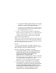
Appendix A Maintenance Log Sheets Level A Maintenance - 15,000 Pages (User) Action Item Part # Clean General cleaning N/A Clean Main charger 705741-001 Clean Precharger 705742-001 Clean Transfer charger 705743-001 Clean See Note 1 Cover glass N/A Replace See Note 2 Toner cartridge 703532-050 Performed By Date Note 1: Every 15,000 pages or 6 paper jams, whichever occurs first.
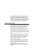
Level B Maintenance - 150,000 Pages (User) Action Item Part # Clean General cleaning N/A Clean Main charger 705741-001 Clean Precharger 705742-001 Clean Transfer charger 705743-001 Clean See Note 1 Cover glass N/A Clean SELFOC lens N/A Vacuum Lamp housing filter 202985-001 Vacuum Cleaning unit 705740-001 See Note 2 Photoreceptor drum 703535-001 Replace See Note 3 Toner cartridge 703532-001 Replace Developer 703548-001 Replace See Note 4 Waste toner bottle 202984-001 Pe
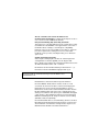
Appendix A Maintenance Log Sheets Level C Maintenance - 600,000 Pages (User) Action Item Part # Clean General cleaning N/A Clean See Note 1 Cover glass N/A Clean SELFOC lens N/A Clean Flash power supply filter N/A See Note 2 Photoreceptor drum 703535-001 Replace Developing Unit 705739-001 Replace See Note 3 Toner cartridge 703532-001 Replace Waste toner bottle 202984-001 Performed By Date Note 1: Every 15,000 pages or 6 paper jams, whichever occurs first.
B Specifications Paper Specifications Paper type Fanfold Paper size Width 7 to 16 inches Length* 1 to 30 inches, in multiples of 1/6 inch. * Measured from main folding/cutting perforation to main folding/ cutting perforation. Tractor pin holes See the table and figure below.
Appendix B 124 Paper Specifications Dimension in Figure Specification Inch Millimeter Pin hole center to folding perforation 1/6, 1/4, 1/ 3, or 1/2 4.23, 6.35, 8.47, 1.20 8 Hole center line to edge of form 0.236 ± 0.028 6.0 ±0.1 1 Hole diameter 0.156 ± 0.004 4.0 ±0.1 N/A Distance between centers of two consecutive holes 0.500 ± 0.002 12.7 ±0.05 5 Max. deviation of holes from their center line 0.004 0.1 6 Max.
Legend: 1) 2) 3) 4) 5) 6) 7) 8) 9) Hole centerline to edge of form Center Line Main Folding/Cutting Perforation Centerline to Centerline Distance between centers of two consecutive holes Center Line Deviation Tractor Pin Hole Pin hole to perforation Fanfold Paper 125
Appendix B Performance Characteristics Paper thickness .010 inch maximum Paper weight 18 to 44 lb. bond (68-165g/m2), 44-125 lb. tag/label (75-204g/m2) Paper feed Automatic paper parking mechanism incorporated Maximum paper stack size 3000 sheets (18 lb.) Folder Perforation Cut 0.12 inches or 3mm minimum Cut to Tie 3:1 minimum Performance Characteristics Printing density 300 x 300 dpi 400 x 400 dpi or 240 x 240 dpi (options) Printing speed 2.78 inches per second.
Host Interfaces Duty cycle 200,000 total pages/month of fanfold paper (11-in. length) Mechanical life 5 years or 12,000,000 pages (11-inch length) Warm-up time 60 sec. max. First page printing time 25 sec. max. MTBF/MPBF 8,000 hours/2,880,000 pages (letter size) 25% print to power on ratio MTTR 2 hour max. (unit exchange Host Interfaces Standard Centronics parallel, Dataproducts parallel, serial RS-232/422 NOTE: Dataproducts parallel interface requires an optional adapter cable.
Appendix B Memory Requirements Emulations Standard LinePrinter Plus Optional PCL5/LP+ PCL5/PGL PCL5/VGL IGP/VGL IGP/PGL IPDS CTHI (if installed) Memory Requirements The L5000 series printers have 32 MB (standard) or 64 MB (optional) of RAM (Random Access Memory), and 8 MB (standard) or 16, 32, or 64 (optional) of Flash Memory. This is standard with all new printer shipments, and all upgraded printers.
Electromagnetic Interference Physical Characteristics and Environment Dimensions (H x W x D) 49 inch H x 30 inch W x 34 inch D In crate: 36 inches H x 58 inches W x 61 inches D Weight 353 lbs. (or 441 lbs.) with options Input voltage range 200 - 240 V +10% 50/60 Hz (47 - 62 Hz) single phase Power consumption 3300 W (operating); wall outlet must be on a 30amp breaker.
Appendix B Physical Characteristics and Environment o Temperature (5F) 80 71 Maximum Temperature/ Humidity Limits 50 30 70 80 Sound level 130 Operating 60 db (A-weighted ) max. Full options Standby state 50 dB (A-weighted) Inclination 1° max.
Index B offline, 94 online, 94 Buttons See Function keys, 29 C Diagrams paper path, 29 Disk drives CANCEL location, 27 function key, 34 Disposal Caution notice, 17 photoreceptor drum, 48 Cleaning fuser unit cover glass, 79 general, 68 DOWN function key, 34 Drum photoreceptor CLEAR disposal, 48 function key, 32 Clearing faults procedure replacing, 42 E with Reprint on Fault disabled, 106 with Reprint on Fault enabled, 108 Clearing service level messages, 65 Consumables Control panel Emulat
Index F Fanfold paper jams, 95 FAULT G Glass cover fuser unit cleaning, 79 H status lamp, 30 Fault clearing procedure with Reprint on Fault disabled, 106 Host interface specifications, 127 I with Reprint on Fault enabled, 108 Fault condition reprinting pages after, 105 Fault messages table, 110 Field service errors requiring, 105 Fonts, 25 Forms, 25 Front panel See Control panel, 29 IGP / PGL Emulation, 24 IGP / VGL Emulation, 24 Impact Printer Emulation, 24 Important notice, 17 Intervals replacemen
Index O LCD See Liquid crystal display, 29 LINE SYNC ONLINE status lamp, 29 LinePrinter Plus emulation, 24 function key, 31 Liquid crystal display (LCD), 29 status lamp, 30 Loading paper, 23 Operator-correctable errors, 105 Location Operator’s panel See Control panel, 29 Output section disk drives, 27 power switch, 27 Log sheets maintenance transport paper jams in, 104 P level A, 120 M Maintenance log sheets Page counts service level, 64 PAGE EJECT level A, 120 Maintenance schedules, 66 Man
Index R Photoreceptor drum disposal, 48 replacing, 42 Physical characteristics, 129 Recharging developing unit See Replacing, developer, 52 Power switch location, 27 Powering On, 27 Precautions safety See Safety.
Index Specifications printer Transport output section paper jams in, 104 electromagnetic interference, 128 U emulations, 128 environment, 129 host interfaces, 127 memory requirements, 128 UP function key, 34 V paper, 123 performance, 126 physical, 129 safety regulations, 129 Vacuum cleaners recommended, 63 W STAND BY status lamp, 30 Waste toner bottle Status lamps, 29 replacing, 40, 42 FAULT, 30 JOB IN PROCESS, 30 LINE SYNC, 29 ONLINE, 30 STAND BY, 30 SYS AVAIL, 30 Switches See Function keys,
Index 136
PRINTRONIX, INC. 14600 Myford Road P.O. Box 19559 Irvine, CA 92623-9559 Phone: (714) 368-2300 Fax: (714) 368-2600 Technical Support: (714) 368-2686 PRINTRONIX Nederland BV P.O. Box 163, Nieuweweg 283 NL-6600 AD Wijchen The Netherlands Phone: (31) 24 6489489 Fax: (31) 24 6489499 PRINTRONIX Schweiz GmbH 42 Changi South Street 1 Changi South Industrial Estate Singapore 486763 Phone: (65) 542-0110 Fax (65) 543-0220 Visit our website at: www.printronix.