® P5000LJ Series Printers User’s Manual
® P5000LJ Series Printers User’s Manual
READ THIS SOFTWARE LICENSE AGREEMENT BEFORE USING THIS PRINTER Software License Agreement CAREFULLY READ THE FOLLOWING TERMS AND CONDITIONS BEFORE USING THIS PRINTER. USING THIS PRINTER INDICATES YOUR ACCEPTANCE OF THESE TERMS AND CONDITIONS. IF YOU DO NOT AGREE TO THESE TERMS AND CONDITIONS, PROMPTLY RETURN THE PRINTER AND ALL ACCOMPANYING HARDWARE AND WRITTEN MATERIALS TO THE PLACE YOU OBTAINED THEM, AND YOUR MONEY WILL BE REFUNDED. Definitions.
Limited Software Product Warranty Printronix warrants that for ninety (90) days after delivery, the Software will perform in accordance with specifications published by Printronix. Printronix does not warrant that the Software is free from all bugs, errors and omissions. Remedy Your exclusive remedy and the sole liability of Printronix in connection with the Software is replacement of defective software with a copy of the same version and revision level.
U.S. Government Restricted Rights Use, duplication or disclosure by the Government is subject to restrictions as set forth in the Rights in Technical Data and Computer Software clause at FAR 242.227-7013, subdivision (b) (3) (ii) or subparagraph (c) (1) (ii), as appropriate. Further use, duplication or disclosure is subject to restrictions applicable to restricted rights software as set forth in FAR 52.227-19 (c) (2).
Trademark Acknowledgments Hewlett-Packard, HP, HP-UX, Bi-Tronics, HP in a circle, Hewlett Packard, PCL and HP rounded rectangle are registered trademarks of Hewlett-Packard Company. AIX, AS/400, IBM, NetView, Proprinter and OS/2 are registered trademarks, and AFP, Intelligent Printer Data Stream, IPDS, Print Services Facility, and PSF are trademarks of International Business Machines Corporation.
Novell and NetWare are registered trademarks of Novell, Inc. PostScript is a registered trademark of Adobe Systems Inc. Solaris is a registered trademark of Sun Microsystems, Inc. Ultrix is a registered trademark of Digital Equipment Corporation. Unix is a registered trademark of X/Open Company Limited. This product uses Intellifont Scalable typefaces and Intellifont technology. Intellifont is a registered trademark of Agfa Division, Miles Incorporated (Agfa).
Table Of Contents 1 Introduction .......................................................... 17 About This Manual ................................................................................17 Warnings, Cautions, And Notes .......................................................17 Printing Conventions Used In This Manual ......................................17 Related Documents..........................................................................18 Printer Overview...................................
Table of Contents 3 Configuring The Printer ........................................ 45 Overview ...............................................................................................45 Configuring The Printer ......................................................................... 45 Operating Modes.............................................................................. 48 The Configurations ...........................................................................
Table of Contents Host Interface Menu ............................................................................115 Bi-Tronics Submenu.......................................................................116 Centronics (Parallel) Submenu ......................................................117 Serial Submenu..............................................................................119 Ethernet Submenu .........................................................................
Table of Contents 7 TCP/IP Configuration ......................................... 157 TCP/IP NIC Configuration ...................................................................157 Before You Begin ........................................................................... 157 Creating Aliases ............................................................................. 158 Methods For Setting TCP/IP Values .............................................. 159 Assign TCP/IP Values...........................
Table of Contents Web Browser/HTTP Problem .........................................................191 Windows NT 4.0 or 2000 Host Setup Problems.............................191 Installing Microsoft TCP/IP Printing................................................191 10 Unix Configuration ............................................. 193 Overview .............................................................................................193 Unix Environment Description ....................................
Table of Contents 12 Novell Configuration For 10/100Base-T Interfaces............................................................ 217 Overview .............................................................................................217 Novell NIC Configuration (10/100Base-T) ........................................... 217 Preferred File Server (NDS & Bindery) .......................................... 218 Setting Password Security (NDS & Bindery)..................................
Table of Contents 14 Extra Features ................................................... 259 NIC Security ........................................................................................259 Users And Passwords ....................................................................259 TCP Access Lists ...........................................................................261 Printer Monitoring And Logging ...........................................................
Table of Contents B Paper Specifications And Forms Design............ 301 Introduction.......................................................................................... 301 General Paper Specifications.............................................................. 301 Paper Guidelines................................................................................. 303 Terms And Definitions .................................................................... 303 Environmental Considerations .........
1 Introduction About This Manual This manual explains how to configure and perform routine service on the Printronix® P5000LJ Series printers for maximum efficiency. Warnings, Cautions, And Notes Read and comply with all information highlighted under special headings: Warning Warning messages call attention to situations that could hurt you or damage the equipment. Caution Conditions that could damage the printer or related equipment.
Chapter 1 About This Manual • Command syntax and examples are formatted as follows: • The Courier font in boldface indicates commands that you type: Example: $ ping ftp.HP.com • Regular Courier font indicates displayed results: Example: ftp.HP.com is alive • Variable values are shown in italics in command syntax, output, and in text. Example: ping ipname Example: ipname is alive Related Documents Following is a list of related documentation shipped with every Printronix P5000LJ printer.
The Printronix P5000LJ Series Printer Family Printer Overview The Printronix P5000LJ Series Printer Family The P5000LJ series of line matrix printers consists of 500, 1000, and 1500 lines per minute (lpm) models packaged in various configurations. All of the models offer software versatility and the latest refinements in line matrix printing technology. The model numbers indicate printing speed and physical configuration: Table 1.
Chapter 1 Printer Overview Additionally, the P5000LJ printer offers the following three emulations as part of its LinePrinter Plus grouping: Proprinter® III XL, Epson® FX-1050, and Serial Matrix P-Series. No matter what emulation is configured, your printer is very easy to use. The message display and indicator on the control panel communicate with you directly and clearly. You can select every function on your printer at the control panel, or you can send commands from the host computer.
Taking Care Of Your Printer Taking Care Of Your Printer Your printer will produce high quality print jobs if it is well taken care of. Periodic cleaning, handling the printer properly, and using the correct printer supplies, such as paper and ribbons, will ensure optimum performance. Chapter 16 explains how to clean the printer, and printer supplies are listed in Appendix A.
Chapter 1 Printer Overview Output Control Depending on the active emulation, the printers have the following output control features: • Four modes for printing text: 1. Correspondence (High Density) 2. Data Processing (DP) (Standard Density) 3. Sparse (high speed) (Sparse Density) 4. OCR A and OCR B • • Selectable forms length and width Character attribute specification: 1. Selectable pitch: normal, expanded, and compressed 2. Emphasized (shadow) printing 3. Automatic underlining and overscoring 4.
Graphics Options Graphics Options The PGL and VGL emulations allow you to create and store forms; generate logos, bar codes, and expanded characters; and create other graphics. Alphanumerics and bar code data are added as the form is printed. Protocols And Emulations A protocol is a set of rules governing the exchange of information between the printer and its host computer. These rules consist of codes which manipulate and print data and allow for machine-to-machine communication.
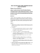
Chapter 1 Printer Overview Line Matrix Printing Your printer is an impact printer; it creates characters by printing ink dots on paper. The dots are printed on an invisible matrix mapped in printer memory (see Figure 2). Dot impressions are made by an array of steel hammers mounted on a rapidly oscillating shuttle. The hammers strike the paper through a moving ink ribbon. Dot Column Matrix visible only to the printer Dot Row Ink dots formed by hammer tips. Character Row Character Column Figure 2.
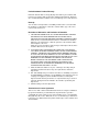
Printing Speed Direction of Shuttle Movement Dot Row Start 1 2 3 4 5 6 7 8* 9* * 10 Number of rows is determined by line spacing. 11 n 1 2 One Text Line * ** Paper Feed Direction This row is used only for lowercase descenders. This row is used for underlining and lowercase descenders. Figure 3. Dot Matrix Line Printing Printing Speed The speed at which text prints is measured in lines per minute (lpm).
Chapter 1 Network Interface Card (NIC) Network Interface Card (NIC) Network Interface Card (NIC) allows you to attach printers on a local area network (LAN) rather than attaching them directly to a host system. Following simple configuration steps, these peripherals can be simultaneously shared with users on the network whether you are using TCP/IP, NetBIOS over TCP/ IP, or IPX (Novell). NIC contains a network interface card to attach itself and the printer to the network.
NIC NIC The NIC at the rear of the printer has two indicator lights and two dipswitches, as shown in Figure 4. Dipswitches 1 2 Shown in OFF (default) position STAT (System Status) NET (Data to Network) Figure 4. Status Indicator Lights and Dipswitches Run and Auto Reset Modes Run Mode is the normal operating state of NIC. Auto Reset mode is entered when the watchdog timer is triggered and the Print Server resets itself.
Chapter 1 Network Interface Card (NIC) Network Indicator The NET LED displays the status of the network link. When the NET LED is on, link integrity is confirmed. The NET LED flashes off for 1/3 second when a data packet is being transferred. When the NET LED is off, the network connection has been severed. Dipswitches On the back of the interface, you will find a small window where you can access two dipswitches labeled 1 and 2 (see Figure 4). The functions of the dipswitches are explained in Table 3.
2 Downloading Function Code In P5000LJ Series Printers Introduction Downloading the function code is equivalent to updating firmware in the printer. This chapter explains how to load function code into P5000LJ printers.
Chapter 2 Introduction Preparation For Downloading There are several function code files available for the P5000LJ printers. The file you use depends on the printer emulation in use. Note Always upgrade the function code to the latest version available that meets the minimum flash memory and DRAM SIMM sizes listed in Table 4. To verify what function code is already installed, observe the control panel display when the printer is online.
Preparation For Downloading Table 4. P5000LJ Series Printers Function Code Chart Description Control Panel Displays: (Emulation in Use) Download File (as shipped) Download Method Minimum Flash/DRAM Required If Serial or Parallel Connected Printers using PCL-II emulation ONLINE-PARL / PCL II* (or) ONLINE-PARL / LP PLUS* xxxxxx.exe (Note 2) Parallel or Serial Port 4 MB Flash 4 MB DRAM Printers using VGL emulation ONLINE-PARL / PCL II / VGL* xxxxxx.
Chapter 2 Loading Function Code To Flash Memory In The Printer Loading Function Code To Flash Memory In The Printer This section contains two loading techniques: • • Note How to load function code through the parallel or serial port of the printer. How to load function code through the Ethernet port using the file transfer protocol (ftp). If Ethernet is installed, you must install the code through the Ethernet port using ftp.
Downloading Software Through the Serial or Parallel Port • Serial or Parallel Port: If you are going to load memory through the serial or parallel port of the printer, see “Downloading Software Through the Serial or Parallel Port” on page 33.. The load commands are different, depending on the printer port you use. These differences are explained in the note following step 22., page 36.
Chapter Note 2 Installing Printer Emulations The default port is CENTRONICS; this is the standard load through the parallel port. If you want to use the default, continue at step 14. 13. Press ⇒ (NEXT) again to cycle through the download ports available in the printer: RS232-9600 (RS-232 serial, 9600 baud) RS232-19.2K (RS-232 serial, 19200 baud) RS232-38.4K (RS-232 serial, 38400 baud) RS232-115K (RS-232 serial, 115000 baud) RS422-9600 (RS-422 serial, 9600 baud) RS422-19.
Downloading Software Through the Serial or Parallel Port 17. Using Windows Explorer, navigate to the appropriate file on the CD based on the printer model number and desired emulation, e.g., T5000 IGP. (See Figure 5.) 18. Make note of the file name, which is a six digit number plus .exe, e.g., 123456.exe. This is the file you will download into the printer. Figure 6. Copying the Emulation File to the Download Directory 19. Copy the file to the download directory.
Chapter 2 Installing Printer Emulations 22. At the command prompt on the computer type: filename.exe -pb where filename.exe is the file name you noted in step 18. This command decompresses the file on the hard drive and copies it as a binary file into the flash memory on the printer controller board. Note If you are loading the file using the LPT2 port on the computer, enter the following command: filename.
Downloading Software Through the Network Interface Card (NIC) Downloading Software Through the Network Interface Card (NIC) 1. Make a printout of all saved configurations. (Installing new software erases all saved configurations. You will use the printouts to restore the printer configurations.) 2. Set the printer power switch to O (Off). 3. On the printer control panel, press and hold down the ONLINE + PAPER ADVANCE keys. Without releasing the keys, power the printer on. Continue holding the keys down. 4.
Chapter 2 Note Installing Printer Emulations You must use the Unzipped directory, since this contains the uncompressed files necessary for NIC download. 9. Make note of the file name, which is a six digit number plus .prg, e.g., 123456.prg. This is the file you will download into the NIC. 10. Copy the file to the download directory. 11. Start a command prompt session. (The Start Menu icon is usually labeled MS-DOS Prompt or Command Prompt.) 12.
Downloading Optional Font Files to Flash Memory 18. When the new program has successfully loaded into flash memory and the printer has reset itself, set the printer power switch to O (off). 19. Unplug the AC power cord from the printer. 20. Remove the CD from the host computer and store it with the printer. 21. Using the configuration printout(s), reconfigure the printer and reload any optional font files. Downloading Optional Font Files to Flash Memory Optional font files are stored on a 3.
Chapter 2 Installing Printer Emulations 8. Press the ⇒ (NEXT) key again to cycle through the download ports available in the printer: RS232-9600 (RS-232 serial, 9600 baud) RS232-9600 (RS-232 serial, 19200 baud) RS232-9600 (RS-232 serial, 38400 baud) RS232-9600 (RS-232 serial, 115000 baud) RS422-9600 (RS422 serial, 9600 baud) RS422-9600 (RS422 serial, 19200 baud) RS422-9600 (RS422 serial, 38400 baud) RS422-9600 (RS422 serial, 115000 baud) DEBUG 9.
Downloading Optional Font Files to Flash Memory Note If you are loading the file using the LPT2 port on the computer, type the following command: copy /b filename.dwn LPT2 (where filename.dwn is a file you noted in step 14.) If you are loading the file using the serial port on the computer, type the following commands: mode COM1:9600,N,8,1,P copy /b filename.dwn COM1 (where filename.dwn is a file you noted in step 14.
Chapter 2 Installing Printer Emulations Table 5. Flash Memory Message Guide Message Explanation Required Action CLEARING PROGRAM FROM FLASH The program successfully loaded into printer RAM and the checksum matched. The old program is now being deleted from flash memory. None DIAGNOSTIC PASSED The printer passed its memory and hardware initialization tests. None ERROR: DC PROGRAM NOT VALID Printer cannot find the data controller program or the validation checksum is corrupt. 1.
Downloading Optional Font Files to Flash Memory Table 5. Flash Memory Message Guide (continued) Message Explanation Required Action ERROR: PROGRAM NEEDS MORE FLASH The printer requires more flash memory in order to run the downloaded program. Add flash memory or use a smaller emulation program. ERROR: PROGRAM NOT COMPATIBLE The printer is not compatible with the downloaded program. Use the correct emulation software option(s) for this model.
Chapter 2 Installing Printer Emulations Table 5. Flash Memory Message Guide (continued) Message Explanation Required Action LOADING PROGRAM INTO FLASH The printer has deleted the previous program from flash memory and is loading the new program into flash memory. None PLEASE WAIT...RESET IN PROGRESS The printer finished loading the program into flash memory and is automatically resetting itself. None RESTORING BOOT CODE Normal download initialization message.
3 Configuring The Printer Overview Note Configuration directly affects printer operation. Do not change the configuration of your printer until you are thoroughly familiar with the procedures in this chapter. This chapter is a tutorial that explains how to configure the P5000LJ printer and the NIC. Configuring The Printer In order to print data, the printer must respond correctly to signals and commands received from the host computer.
Chapter 3 Configuring The Printer Cabinet Model Message Display Status Indicator CLEAR UP SHIFT SET TOF PREV NEXT PAGE L ADJ ENTER L.P.I. ADJ DOWN ON LINE FF LF VIEW Pedestal Model Status Indicator Message Display Up Set TOF L.P.I. Adj Down On Line FF Prev Next Shift Clear LF View Enter Page L Adj Primary Keys Secondary Keys (Raise the printer cover to access these keys.) Figure 8.
OFFLINE CONFIG. CONTROL page 77 Load Config. Save Config. Print Config. Delete Config. Power-Up Config. Protect Configs.
Chapter 3 Configuring The Printer Operating Modes The printer has two operating modes: online and offline. When the printer is online, it is controlled by the host computer and prints data sent by the host computer. When the printer is offline, communication with the host is interrupted so you can load paper, change ribbons, or test and configure the printer. Activate configuration settings with the ENTER key, which enters your new setting into printer memory.
Changing And Saving Parameter Settings Changing And Saving Parameter Settings You can change a parameter setting, such as line spacing or forms length, by pressing keys on the control panel or by sending emulation control codes in the host data stream. When you change a parameter, it is active as long as the printer is on. This is true whether you used the control panel or sent a control code from the host. If you use the control panel, you can save the parameters as a customized configuration.
Chapter 3 Configuring The Printer Factory Default Configuration Values The factory default values are permanently stored in memory as a configuration and cannot be modified or erased. The configuration values for the Bi-Tronics parallel interface and NIC interface are displayed on the following pages. Bi-Tronics Parallel Interface ACTIVE EMULATION PCL-II Primary Char. set ID Symbol Set Pitch Density Second Char. set ID Symbol Set Pitch Density Page Length Rep. Max.
Factory Default Configuration Values Font Attributes Typeface Prop. Spacing Bold Print Italic Print Slashed Zero Page Format Form Length Abs. Length IN Abs. Length MM Funct. of lines Form Width Abs. Width IN Abs.
Chapter 3 Configuring The Printer NIC Interface ACTIVE EMULATION PCL-II Primary Char. set ID Symbol Set Pitch Density Second Char. set ID Symbol Set Pitch Density Page Length Rep. Max. Line Width Face, CPI Delay Graphics Density Perforation Skip Display Functns Line Terminator LF After CR CR After LF CR after FF CR After VT PTX Linefeed LPI Adjust Page L./Lines Page L./Inches Config.
Factory Default Configuration Values Page Format Form Length Abs. Length IN Abs. Length MM Funct. of lines Form Width Abs. Width IN Abs.
Chapter 3 Changing Parameters Changing Parameters A configuration consists of several parameters. The factory configuration is PCL-II emulation using the Bi-Tronics interface. You can keep this configuration to print your jobs, or if your print job requires a different setting such as a serial interface, follow the procedure outlined in Table 6. Example The example below describes how to change the Unidirectional parameter from disable to enable.
Example Table 6. Parameter Change Example Procedure (continued) Step 3. Key Result ENTER SWITCH UNLOCKED + Notes Allows you to make configuration changes. OFFLINE CONFIG. CONTROL 4. UNTIL 5. PRINTER CONTROL Unidirectional 6. Unidirectional Disable* 7. OR 8. OFFLINE PRINTER CONTROL ENTER Unidirectional Enable Unidirectional Enable* Cycle through the choices. An asterisk (*) indicates this choice is active. TO SAVE YOUR CHANGES AS A CONFIGURATION THAT IS STORED IN MEMORY: 1. UNTIL 2. 3.
Chapter 3 Changing Parameters Saving Your New Configuration * = Factory Default CONFIG. CONTROL Load Config. Save Config. Print Config. Delete Config. Power-Up Config. Protect Configs. 1 2 3 4 5 6 7 8 A configuration must be saved in order to load it later. You can save up to eight configurations to meet different print job requirements.
Saving Your New Configuration Table 7. Saving Configurations Step 1. 2. 3. Key Result Notes Make sure the printer is on. Raise the printer cover (on cabinet models). ON LINE OFFLINE CONFIG. CONTROL ENTER SWITCH UNLOCKED + Allows you to make configuration changes. OFFLINE CONFIG. CONTROL 4. CONFIG. CONTROL Load Config. 5. UNTIL 6. CONFIG. CONTROL Save Config. Save Config. 1* 7. OR Save Config. 2 Press until the desired number (1-8) displays.
Chapter 3 Changing Parameters Printing The Current Configuration * = Factory Default CONFIG. CONTROL Load Config. Save Config. Print Config. Delete Config. Power-Up Config. Protect Configs. Current* Factory Power-Up All 1 2 3 4 5 6 7 8 The configuration printout lists the stored parameters. You can print any or all of the configurations shown above. Configurations 1-8 are the customized configurations. To print a configuration, follow the procedure in Table 8.
Printing The Current Configuration Table 8. Printing Configurations Step 1. 2. 3. Key Result Notes Make sure the printer is on. Raise the printer cover (on cabinet models). ON LINE OFFLINE CONFIG. CONTROL ENTER SWITCH UNLOCKED + Allows you to make configuration changes. OFFLINE CONFIG. CONTROL 4. CONFIG. CONTROL Load Config. 5. UNTIL 6. Print Config. Current* 7. OR 8. 9. 10. 11. 12. CONFIG. CONTROL Print Config. ENTER Print Config. All Press until the desired option displays.
Chapter 3 Changing Parameters Loading Configuration Values * = Factory Default CONFIG. CONTROL Load Config. Save Config. Print Config. Delete Config. Power-Up Config. Protect Configs. 0* 1 2 3 4 5 6 7 8 You can load any of the eight customized configurations or the factory default configuration, Configuration 0. Its list of parameters begins on page 50. The loaded configuration remains active as long as the printer is on.
Loading Configuration Values Table 9. Loading Configurations Step 1. 2. 3. Key Result Notes Make sure the printer is on. Raise the printer cover (on cabinet models). ON LINE + OFFLINE CONFIG. CONTROL ENTER SWITCH UNLOCKED Allows you to make configuration changes. OFFLINE CONFIG. CONTROL 4. CONFIG. CONTROL Load Config. 5. Load Config. 1* 6. OR 7. ENTER Load Config. 4 Loading Saved Configuration Load Config. 4* 8. 9. 10.
Chapter 3 Changing Parameters The Power-Up Configuration * = Factory Default CONFIG. CONTROL Load Config. Save Config. Print Config. Delete Config. Power-Up Config. Protect Configs. 0* 1 2 3 4 5 6 7 8 When you power on the printer for the first time, it loads configuration 0 which is the factory default configuration.
The Power-Up Configuration Table 10. Setting The Power-Up Configuration Step 1. 2. 3. Key Result Notes Make sure the printer is on. Raise the printer cover (on cabinet models). ON LINE OFFLINE CONFIG. CONTROL ENTER SWITCH UNLOCKED + Allows you to make configuration changes. OFFLINE CONFIG. CONTROL 4. CONFIG. CONTROL Load Config. 5. UNTIL 6. Power-Up Config. 0* 7. OR 8. 9. 10. 11. CONFIG. CONTROL Power-Up Config. ENTER + ON LINE Power-Up Config.
Chapter 3 Changing Parameters Deleting Configurations * = Factory Default CONFIG. CONTROL Load Config. Save Config. Print Config. Delete Config. Power-Up Config. Protect Configs. 1* 2 3 4 5 6 7 8 You can delete any of your customized configurations. You cannot, however, delete the configuration 0, which is the factory preset configuration. The Protect Configs. parameter must be set to disable before you may delete a configuration (see page 66).
Deleting Configurations Table 11. Deleting Configurations Step 1. 2. 3. Key Result Notes Make sure the printer is on. Raise the printer cover (on cabinet models). ON LINE OFFLINE CONFIG. CONTROL ENTER SWITCH UNLOCKED + Allows you to make configuration changes. OFFLINE CONFIG. CONTROL 4. CONFIG. CONTROL Load Config. 5. UNTIL 6. Delete Config. 1* 7. OR 8. CONFIG. CONTROL Delete Config. ENTER Delete Config. 3 Deleting Configuration Press until the desired number (1-8) displays.
Chapter 3 Changing Parameters Protecting Your Configurations * = Factory Default CONFIG. CONTROL Load Config. Save Config. Print Config. Delete Config. Power-Up Config. Protect Configs. Disable* Enable To save or delete a configuration you must set the Protect Configs. option to disable.
Connecting To The Network Configuring NIC Connecting To The Network To attach the NIC to a network, plug the network cable into the NIC connector (see Figure 10). Watch the LEDs in the rear of the printer as they cycle through the power on self-test. When the test is complete, the STAT led will flash. A A Network Connector Figure 10. Physical Setup Configuration Setup There are two parts to a NIC setup: 1. Configuring the NIC so it can be seen on the network. This involves network related settings (e.
Chapter 3 Configuring NIC Note Some network environments do not require any network settings to be configured on the NIC. However, all network setups require configuration on the host end. Configuration Using The Printer Control Panel NIC settings can be set from the printer control panel. The procedure is described below. Note When the printer is first powered on, the messages “Waiting for the Ethernet Adapter” and “Ethernet Detected” will display on the LCD.
Configuration Alternatives 9. Press the DOWN arrow key. 10. Press the LEFT or RIGHT arrow key to select the desired value. 11. Press the ENTER key to make the selection. An asterisk appears to the right of the value. 12. Press the UP arrow key and you will be returned to step 8. When you are finished changing parameters, exit the configuration menus and lock the ENTER key. (For instructions, refer to “Locking And Unlocking The ENTER Key” on page 48.
Chapter 3 Configuring NIC Remote Shell A TCP/IP command that helps configure print server settings remotely. A TCP/IP host uses this command to remotely execute a single command on the NIC. Example: rsh spike list prn This command remotely executes the npsh command list prn on the NIC named spike. Configuration Using a Web Browser NIC settings can be configured over TCP/IP through a standard Web browser. The NIC Web pages provide a handy way to access some of the commands built into the print server.
Configuration Alternatives Figure 11.
Chapter 72 3 Configuring NIC
4 The Configuration Menus Overview Once you have familiarized yourself with the configuration process using the tutorial information in Chapter 3, you are ready to complete your configuration of the printer. This chapter provides descriptions for each parameter provided by the configuration menus. Figure 12 shows the configuration main menu and its first level parameters.
Chapter 4 Configuration Main Menu Configuration Main Menu OFFLINE CONFIG. CONTROL (see page 77) Load Config. 0* - 8 Save Config. 1* - 8 Print Config. Current* Factory Power-Up All 1-8 Delete Config. 1* - 8 Power-Up Config. 0* - 8 Protect Configs.
HOST INTERFACE (see page 115) ETHERNET PARAMS (see page 125) Serial (cont.) Bi-Tronics* IP Address Stop Bits Prime Signal xxx.xxx.xxx.xxx 1* Disable* Gateway Address 2 Enable xxx.xxx.xxx.xxx Parity TOF Action Subnet Mask None* Reset* xxx.xxx.xxx.
Chapter 4 Configuration Main Menu The first-level configuration menu options are briefly described below: • CONFIG. CONTROL. Allows you to save, print, load, and delete entire sets of configuration parameters. These options are described briefly in this chapter and covered in detail in Chapter 3. • ACTIVE EMULATION. Allows you to select either Hewlett-Packard's Printer Control Language (PCL-II) or LP Plus.
Config. Control Menu CONFIG. CONTROL Load Config. 0* 1 2 3 4 5 6 7 8 Save Config. 1* 2 3 4 5 6 7 8 Print Config. Current* Factory Power-up All 1 2 3 4 5 6 7 8 Delete Config. Power-up Config. 0* 1 2 3 4 5 6 7 8 1* 2 3 4 5 6 7 8 Protect Configs. Disable* Enable To view options, press: Down Up Next Prev To select an option, press ENTER. To return to main menu, press CLEAR. To exit menu, press ON LINE. * = Default Setting The CONFIG.
Chapter 4 Config. Control Menu Save Config. This option allows you to save up to eight unique configurations to meet different print job requirements, which eliminates the need to change the parameter settings for each new job. The configurations are stored in memory. They will not be lost if you turn off the printer. Configuration 0 is a factory-preset configuration, which cannot be changed or saved. See page 56 for a detailed description and sample procedure. Note If the Protect Configs.
Active Emulation Menu ACTIVE EMULATION PCL-II* LP PLUS IGP/PGL & LP+1 IGP/VGL (CODE-V) & LP+1 The ACTIVE EMULATION menu determines what emulations are available. • • PCL-II. The default. The PCL-II emulation is active. • IGP/PGL & LP+ and IGP/VGL (Code V) & LP+. The ACTIVE EMULATION function also allows you to activate either the PGL or the Code V emulation. There are two methods for selecting the desired emulation. The first is by selecting the emulation directly from the printer menu.
Chapter 4 Emulation Menu Emulation Menu EMULATION PCL-II* LP PLUS (see page 81) (see page 86) IGP/PGL & LP+1 IGP/VGL (CODE-V) & LP+1 (see page 102) (see page 107) To view options, press: Down Up Next Prev To select an option, press ENTER. To return to main menu, press CLEAR. To exit menu, press ON LINE. * = Default Setting = If installed 1 The EMULATION menu is the gateway to configure the emulations available with the P5000LJ printer.
PCL-II Emulation PCL-II Emulation * = Factory Default EMULATION (from page 80) PCL-II Secondary Char. Set Page Length Rep. Max. Line Width Inches/Page* Lines/Page 0* - 109, xx Symbol Set (see next page) Pitch 10*, 12, 13.3 15, 16.67, 20 Density Data Processing* NLQ OCR-A OCR-B High Speed 13.2 inches* 13.6 inches Primary Char. Set ID 0* - 109, xx Symbol Set (see next page) Pitch 10*, 12, 13.3 15, 16.67, 20 Density Data Processing* NLQ OCR-A OCR-B High Speed Graphics Density 60 dpi* 70 dpi Page L.
Chapter 4 Emulation Menu Primary Char. set (from previous page) Secondary Char. Set (from previous page) Symbol Set Symbol Set Roman-8[8U]* Turkish-8[8T] Arab-8[8V] Cyrillic[8R] PC858 MtLi[13U] MC Text[12J] Roman-9[4U] Latin-9[9N] Win3.0Lat-1[9U] Japan Postnet Katakana Post ASCII[0U] Math Sym[0A/0M] LineDraw[0B/0L] IS0 Den/Nor[0D] Roman Ext.
PCL-II Emulation Page Length Rep. • Inches/Page. All page length calculations are based on the inches displayed on the panel. • Lines/Page. All changes in LPI or density will be changed accordingly. The length of the page is the number of lines per inch, or lpi. For example, if the form in use is 82 lines at 6 lpi, the page is physically 13.67 inches. Since 13.67 inches is not selectable from the Length in Inches menu, change the representation to lines, then set the number of lines to 82.
Chapter 4 Emulation Menu PTX Linefeed • Disable. The default. Linefeed is to be performed as calculated from the bottom of the graphics or barcode, thereby disrupting the vertical text alignment. • Enable. The Linefeed moves to the next line as calculated from the Top of Form position, thereby retaining vertical text alignment. When printing graphics or bar codes, you may want to set the PTX Linefeed parameter to Enable to maintain text alignment.
PCL-II Emulation Symbol Set Print This option prints a list of all the available sets. The character set number prints to the left of the character set sample. Reset Cmd CFG Ld When the printer receives a host data stream reset command in addition to resetting printer variables, the selected configuration will be loaded. • Disable. The printer ignores the reset command when it is received and continues to use the currently loaded configuration. • Power-Up Config.
Chapter 4 Emulation Menu LP Plus Emulation EMULATION (from page 80) LP PLUS Printer Protocol Print Char. Set CPI/LPI Select Select CPI 10.0 CPI* 12.0 CPI 15.0 CPI 17.1 CPI 20.0 CPI Select LPI 6.0 LPI* 8.0 LPI 10.3 LPI Font Attributes Page Format Typeface Data Processing* NLQ OCR-A OCR-B High Speed NLQ Sans Serif Prop. Spacing Form Length Disable* Enable Bold Print Abs. Length IN Disable* 11.0* inches Enable (0.1-24) Italic Print Abs. Length MM Disable* 279.4* mm. Forward Slant (0.1-609.
LP Plus Emulation Printer Protocol Select the LinePrinter+ protocol you wish to use. Refer to the PCL-II/ LinePrinter Plus Technical Reference Manual for more information. Print Char. Set When this selection is displayed and the ENTER key is pressed, the current character set is printed. CPI/LPI Select This parameter lets you specify the characters per inch (cpi) value and lines per inch (lpi) value. Font Attributes Typefaces • Data Processing.
Chapter 4 Emulation Menu Bold Print • • Disable. Text is printed normally. Enable. Text is printed with a heavy line thickness. Italic Print • • • Disable. Text is printed normally. Forward Slant. Text is printed with a forward slant. Backward Slant. Text is printed with a backward slant. Slashed Zero This parameter allows you to print the numeral “0” with or without the slash. This option applies to all character sets except OCR-A and OCR-B. • • Disable. Zero is printed without a slash. Enable.
LP Plus Emulation Reset Cmd CFG Ld When the printer receives a host data stream reset command in addition to resetting printer variables, the selected configuration will be loaded. • Disable. The printer ignores the reset command when it is received and continues to use the currently loaded configuration. • Power-Up Config. The power-up configuration is loaded when the reset command is received. • Current Config.
Chapter 4 Emulation Menu P-Series Emulation * = Factory Default Printer Protocol (from page 86) P-Series Control Code 06 8.0 LPI* 10.3 LPI 6.0 LPI Control Code 08 Elongated* Backspace Select SFCC 1* (0-7F hex) Auto LF Define CR Code CR = CR* CR = CR + LF Disable* Enable EVFU Select Alt.
P-Series Emulation Control Code 06 Control Code 06 defines the function of ASCII code hex 06 (ACK). You can select an alternate line spacing of 6, 8, or 10.3 LPI. Control Code 08 Control Code 08 defines the function of ASCII code hex 08 (BS). You can define the code to output an elongated character or a backspace. Define CR Code This option controls the action of the printer when it receives a Carriage Return code (hex 0D) from the host computer.
Chapter 4 Emulation Menu Select SFCC This parameter allows you to select which ASCII codes will function as the Special Function Control Code (SFCC) command delimiter. P-Series codes can use hex 00 through hex 7F. Options include the following: • • • • • Note ESC (hex 1B) SOH (hex 01) ETX (hex 03) CIRCUMFLEX (hex 5E)—also called caret (^) TILDE (hex 7E)—(~) SOH, ETX and ESC are non-printables. The characters (^) and (~) are printable.
Proprinter XL Emulation Proprinter XL Emulation * = Factory Default Printer Protocol (from page 86) Proprinter XL Define CR Code CR = CR* CR = CR + LF Auto LF Enable* Disable Define LF Code LF = LF* LF = CR + LF FF valid at TOF Enable* Disable Character Set Alt.
Chapter 4 Emulation Menu Auto LF This option defines the printer actions when print data is received past the forms width setting. • Enable. Performs an automatic carriage return and line feed when data is received past the forms width. • Disable. Discards any data past the forms width. Define LF Code • LF = LF. Does not perform an automatic carriage return when a line feed command is received. The next print position will be the current print position of the next line. • LF = CR + LF.
Epson FX Emulation Epson FX Emulation * = Factory Default Printer Protocol (from page 86) Epson FX Define CR Code CR = CR* CR = CR + LF Auto LF Enable* Disable Define LF Code LF = LF* LF = CR + LF Printer Select Disable* Enable Character Set 20 CPI Condensed Enable* Epson Set* ASCII (USA)* Disable French German English Danish I Swedish Italian Spanish I Japanese Norwegian Danish II Spanish II Latin Am I French Canadian Latin Am II OCR-A OCR-B Latin 2 8859-2 Latin 2 852 Cyrillic 866 Bulgarian Latin
Chapter 4 Emulation Menu Define CR Code The Define CR Code option controls the action of the printer when it receives a Carriage Return code (hex 0D) from the host computer. If this feature is enabled, each time the printer receives a Carriage Return, it inserts an additional Line Feed code (hex 0A) into the data stream. Do not use this feature if the host computer sends Line Feeds to the printer. • • CR = CR. Does not insert an extra Line Feed after each Carriage Return. CR = CR + LF.
Serial Matrix Emulation Alt. Set 80-9F • Control Code. Interprets data in the range of hex 80 through hex 9F as a control code. • Printable. Prints data in the range of hex 80 through hex 9F. Serial Matrix Emulation * = Factory Default Printer Protocol (from page 86) Serial Matrix Control Code 06 Define CR Code 8.0 LPI* 10.3 LPI 6.0 LPI CR = CR* CR = CR + LF Auto LF Enable* Disable Alt.
Chapter 4 Emulation Menu Auto LF The Auto LF option defines the printer actions when print data is received past the forms width setting. • Enable. Performs an automatic carriage return and line feed when data is received past the forms width. • Disable. Discards any data past the forms width. Overstrike This option enables you to print bold characters. • Enable. Turns on bold print. When enabled, overstrike printing slows down the printer. • Disable. Turns off bold print.
Serial Matrix Emulation Serial Matrix Character Set Menu * = Factory Default Character Set (from page 97) IBM PC* Multinational Primary Subset ASCII (USA)* ASCII (USA)* EBCDIC French German English Danish Swedish Italian Spanish Japanese French Canadian Latin American Danish II Spanish II Latin Am II Extended Subset Code Page 437* Code Page 850 ECMA Latin 1 DEC Mult. Primary Subset ASCII (USA)* ASCII (USA)* French German German English Swedish Norw.
Chapter 4 Emulation Menu P-Series XQ Emulation * = Factory Default Printer Protocol (from page 86) P-Series XQ Control Code 06 6.0 LPI 8.0 LPI* 10.3 LPI HS Print char 02 STX* char 03 ETX char 09 HT Define CR Code CR = CR* CR = CR + LF EVFU Select Enable* Disable Auto LF Disable* Enable Upr. Case Select Disable* Enable Define LF Code Compressed Print LF = CR + LF* LF = LF char 01 SOH* char 03 ETX char 09 HT Elong/Alt.
P-Series XQ Emulation Define LF Code • LF = CR + LF. Forces an automatic carriage return with each line feed command received. The next print position is print position 1 of the next line. • LF = LF. Does not perform an automatic carriage return when a line feed command is received. The next print position will be the current print position of the next line. Compressed Print Controls which host command sets compressed printing. • • • CHAR 01 SOH CHAR 03 ETX CHAR 09 HT Elong/Alt.
Chapter 4 Emulation Menu Slew Relative “Slewing” is rapid vertical paper movement. This parameter determines the number of lines slewed (either 1-15 lines or 1-16 lines) when an EVFU Slew Relative command is received. IGP/PGL Emulation The IGP/PGL emulation can be configured either through the printer’s front panel or from the host computer with control codes. For a detailed description of configuration with control codes, see the PGL Technical Reference Manual.
IGP/PGL Emulation Define CR Code (Carriage Return) This parameter forces the printer to insert an automatic Line Feed code into the data stream whenever a Carriage Return code occurs. This is to be used only if the host computer does not send Line Feeds to the printer. • CR = CR. Does not perform a line feed. The next print position will be print position 1 of the current line. • CR = CR + LF. Performs an automatic line feed. The next print position will be print position 1 of the next line.
Chapter 4 Emulation Menu Select Font This parameter allows you to select a font for the IGP/PGL feature. The default is 0, which is U.S. ASCII. The following values are valid choices: 0 1 2 3 4 5 6 7 8 9 10 11 U.S. ASCII German Swedish Danish Norwegian Finnish English Dutch French Spanish Italian Turkish Values 12-23 are undefined and will default to 0. You can set values 24-31 to specific fonts; refer to the USET command in the IGP/PGL Technical Reference Manual.
IGP/PGL Emulation Ext Execute Copy • Disable. Dynamic data, overlay data, etc. are not allowed if the optional Form Count parameter (number of forms to print) is specified as part of the Execute command. (This setting is IGP-100 compatible.) • Enable. Dynamic data, overlay data, etc. are allowed within a form in which the Form Count parameter is specified in the Execute command. In this case, the exact same form (with identical dynamic data) is printed for whatever the Form Count is.
Chapter 4 Emulation Menu IGP100 Compatbl. This option instructs the IGP/PGL to behave similarly to the IGP-100 with respect to certain commands. All new users with new applications should select the Disable option. Selecting this mode insures the printer will behave as described in this manual. • • Disable. The IGP does not emulate the IGP-100 mode. Enable. The IGP emulates the IGP-100 version.
IGP/VGL (Code V) Emulation IGP/VGL (Code V) Emulation The IGP/VGL (Code V) emulation can be configured either through the printer’s front panel or from the host computer with control codes. For a detailed description of configuration with control codes, see the QMS Code V Technical Reference Manual. For information on configuring the emulation through the printer’s front panel, see the submenu below and the parameter descriptions that follow.
Chapter 4 Emulation Menu * = Factory Default Graphics Options (from page 107) Slashes in Zeros Enable* Disable UPC Descenders Disable* Enable Ignore Dots Disable* Enable Append Rotated Disable* Enable Ignore Spaces Rot. Char Size Adjusted* Not Adjusted Disable* Enable Truncate Alpha Enable* Disable Midline PY Disable* Enable True Vert 1/10 Disable* Enable Convert to U/C Disable* Enable Absorb After ^PY Absorb All* Disable Absorb Motion Absorb After ^PN Disable* Enable IGP110 Compatbl.
IGP/VGL (Code V) Emulation Free Format • Disable. The default. • Enable. Selects free format mode as the power-up default, and selects the graphics mode ^PY as the power-up default. Free format causes the Code V to ignore carriage returns, line feeds, and all characters below hex 20 sent from the host. Mgnum Conversion • Disable. The default. • Enable. Selects the graphics mode ^PY as the power-up default. LPI The number of lines to be printed per inch.
Chapter 4 Emulation Menu Truncate Alpha When enabled, this parameter prevents the printing of Error 48 (Element Off Page Error) if alphanumeric data, including spaces, extends beyond the right side of the form. True Vert 1/10 • Disable. A vertical 1/10 of an inch parameter is used as 7/72 of an inch. The absolute move is slightly smaller than expected. For example, a one inch move would be 70/72 of an inch. Vertical moves that have the same value will be identical in length. • Enable.
IGP/VGL (Code V) Emulation Midline PY (includes ^PN) • Disable. The Graphics mode Enable command, ^PY, must be the first three characters of a line. • Enable. The ^PY or ^PN can occur anywhere in a line. Convert to U/C • Disable. Lowercase characters are printed normally. • Enable. All lowercase alphabetic characters are converted to uppercase. Absorb After ^PN • Disable. All line terminators that immediately follow the ^PN command are sent to the printer and processed. • Enable.
Chapter 4 Emulation Menu Offpage Errors • Disable. Does not report errors for elements that start or end beyond the right edge of the page. • Enable. Reports errors for elements that start or end beyond the right edge of the page. Barcode Errors • Enable. An error message will print when invalid bar code data is encountered. • Note Disable. Code V will not print an error for illegal bar code data; the bar code will be skipped.
IGP/VGL (Code V) Emulation ISO Char Set This parameter allows you to select a font for the IGP/VGL (Code V) feature. The default is 0, which is U.S. ASCII. The following values are valid choices: 0 1 2 3 4 5 6 7 8 9 10 U.S. ASCII United Kingdom Swedish/Finnish Norwegian/Danish Japanese German French Italian Spanish PC Subset Code V Version I PI Control Printer PI • • Disable. The ASCII emulation is configured with the PI line disabled. Enable. The ASCII emulation is configured with the PI line enabled.
Chapter 4 Maint/Misc Menu Maint/Misc Menu MAINT/MISC Hex Dump Mode Disable* Enable Power-up State Online* Offline Display Language English* Italian French German Spanish Power Stacker1 Enable* Disable To view options, press: Down Up Next Prev To select an option, press ENTER. To return to main menu, press CLEAR. To exit menu, press ON LINE. * = Default Setting = If installed 1 Hex Dump Mode A hex code printout (or hex dump) translates all incoming data to hexadecimal equivalents.
IGP/VGL (Code V) Emulation Power Stacker This parameter, which is only presented with the 1500QS model, allows you to enable (the default) or disable power stacker operation. Note When running short print jobs with the power stacker enabled, it automatically moves to the top position. Note When you press the Online button, the stacker automatically moves down one inch. When you press the Offline button, the stacker moves up approximately one inch.
Chapter 4 Host Interface Menu Note The printer will not work online unless the type of interface selected from the HOST INTERFACE menu matches the type of interface in your host computer. The interface in your host computer is the one that connects to the data cable of the printer. For example, if the interface in your computer is a serial interface, then the serial interface must be selected from the HOST INTERFACE menu in the printer.
Centronics (Parallel) Submenu TOF Action • Reset. A form feed is performed before a warm start when the prime signal is asserted from the host. This setting is used only if the Prime Signal parameter is enabled. • Do Nothing. No form feed is performed on reset. Buffer Size in K This option configures the amount of memory allocated for the Bi-Tronics port buffer. You can designate the size of the printer buffer from 1 through 16 Kbytes.
Chapter 4 Host Interface Menu Data Bit 8 • • Enable. Allows access to the extended ASCII character set. Disable. The printer interprets bit 8 of each incoming data character as a zero, regardless of its actual setting. PI Ignored The PI (Paper Instruction) signal is used to control vertical paper motion. • Enable. Ignores the PI signal and treats the data as characters or control codes. • Disable. Causes the printer to interpret the eight data lines as VFU commands when the PI signal is true.
Serial Submenu TOF Action • Reset. A form feed is performed before a warm start when the prime signal is asserted from the host. This setting is used only if the Prime Signal parameter is enabled. • Do Nothing. No form feed is performed on reset. Buffer Size in K Configures the amount of memory allocated for the Centronics parallel port buffer. The default is 1 Kbyte, but you can specify between 1 and 16 Kbytes, in 1-Kbyte increments.
Chapter 4 Host Interface Menu Interface Type Allows you to select either the RS-232 (the default) or RS-422 serial port interface. Data Protocol You can select one of the following serial interface protocols to meet the host interface requirements. • XON / XOFF. The default. The printer controls the flow of communication from the host by turning the transmission on and off.
Serial Submenu Word Length Sets the length of the serial data word. The length of the data word can be set to 7 or 8 bits, and must match the corresponding data bits setting in the host computer. The default is 8 bits. Stop Bits Sets the number of stop bits in the serial data word. Either one or two stop bits can be selected. The setting must match the corresponding stop bit setting in the host computer. The default is 1 bit. Parity Set for odd parity, even parity, mark, sense, or no parity.
Chapter 4 Host Interface Menu Ethernet Submenu * = Factory Default Ethernet (from page 115) Buffer Size in K 16* (1-16) The Ethernet interface allows you to locate the printer on a LAN rather than attach the host directly into the printer. Buffer Size in K This option configures the amount of memory allocated for the Ethernet buffer. The default is 16 Kbytes. You can specify between 1 and 16 Kbytes, in 1-Kbyte increments.
Auto Switching Submenu Auto Switching Submenu * = Factory Default Auto Switching (from page 115) Parallel Hotport Serial Hotport Port Type Bi-Tronics Centronics Ethernet Disable Trickle Time 1/4 sec* 1/2 sec 1 sec 2 sec 4 sec 8 sec 16 sec Off Timeout 10 sec.* (1-60) Report Status Disable* Enable Port Type RS-232* RS-422 Disable Trickle Time 1/4 sec* 1/2 sec 1 sec 2 sec 4 sec 8 sec 16 sec Off Timeout 10 sec.
Chapter 4 Host Interface Menu Trickle Time When the printer is printing data from a host and a second job is received by the printer from a different host, Trickle Time prevents the second host from timing out while it is waiting for its data to be printed. In order to support this feature, the port has to be able to accept data from the host and store it for future use.
Auto Switching Submenu Ethernet Params Menu ETHERNET PARAMS IP Address Gateway Address Subnet Mask MAC Address xxx.xxx.xxx.xxx xxx.xxx.xxx.xxx xxx.xxx.xxx.xxx hhhhhhhhhhhh Novell Frame PPM Port Number Ethernet 802.2* 802.2 Snap Auto Sensing Ethernet II Ethernet 802.3 3001* (0-65535) PPM Port Timeout 100 secs.
Chapter 4 Ethernet Params Menu Gateway Address A gateway address is the IP address of a hardware device (gateway) that translates data between two incompatible networks, which can include protocol translation. Subnet Mask A binary value used to divide IP networks into smaller subnetworks or subnets. This mask is used to help determine whether IP packets need to be forwarded to other subnets. MAC Address This menu item is the Manufacturer’s Assigned Number, and is unique for each printer.
Auto Switching Submenu Ethernet Speed This menu option only appears if a 10/100Base-T network interface card (NIC) is installed. The Ethernet Speed menu allows compatibility with different systems and networks. The factory default is Auto Select. • Auto Select. (the default) This setting tells the 10/100Base-T NIC to perform an auto detection scheme and configure itself to be 10 Half Duplex, 10 Full Duplex, 100 Half Duplex, or 100 Full Duplex. • 10 Half Duplex.
Chapter 4 Printer Control Menu Unidirectional The Unidirectional feature affects both print quality and printing speed. By setting this feature, you can configure the printer to print in both directions of the shuttle sweep (bidirectional), or to print in one direction only (unidirectional). You might want to enable this feature when printing bar codes, high quality text and graphics, or other printing that requires precise vertical alignment.
Auto Switching Submenu Power Saver Time Power Saver is also referred to as the ENERGY STAR® Office Equipment Program. The Power Saver feature places the printer in “sleep mode” when the printer has not been used for a specified number of minutes. In sleep mode the printer is in low-energy idle state, all fans and higher voltages are off, and only +5Vdc logical circuits are active. You can designate the number of minutes after which the printer will go into sleep mode.
Chapter 4 Diagnostics Menu Printer Tests The printer tests are used to check the print quality and printer operation. Note Your Customer Service Engineer typically runs these tests. They are described in more detail in the P5000LJ Series Printers Maintenance Manual. The Printer Tests parameters are described below. (For test running procedures, see page 278.) • Shift Recycle.
Auto Switching Submenu Note The printer must be printing the phase pattern of “H’s” when the Phasing Value is changed or the new phasing value will not be written into nonvolatile RAM (NVRAM). If the value is changed when not printing, the printer will return to its default phasing value when powered off and then back on. • Paperout Adj. It is recommended that only a Hewlett-Packard Customer Service Engineer run this test. The Paperout Adj.
Chapter 4 RibbonMinder Print Statistics You can view various printer statistics, such as hours of usage, and refer to these figures for preventive maintenance purposes. Printer statistics accumulate continuously; they do not reset when you turn off the printer. All of the printer statistics are set to zero at the factory after burn-in testing. • On. The cumulative time in hours the printer has been powered on. The range is from 0 to 30,000 hours. • Print.
RibbonMinder Menu Note Once you have set up options for RibbonMinder, it works without attention. When you begin printing with RibbonMinder enabled, the message display shows a ribbon life value of 100%. The ribbon life decreases as the ink is consumed. RibbonMinder Menu * = Factory Default **Defaults: Cab - Gold Ser 90 Ped - Gold Ser 30 P5220 - Gold 2000 RIBBONMINDER New Ribbon Ribbon Action Ribbon Type** Ribbon End Point Press ENTER to reset ribbon life to 100%.
Chapter 4 RibbonMinder • Fault immed. When FAULT IMMED. mode is selected, and the ribbon life reaches 0%, the message RIBBON INK OUT/ CHANGE RIBBON displays on the control panel. The printer stops and goes into fault condition. To complete the job in progress, the user must press the CLEAR key. This allows the printer to continue printing for approximately two minutes.
RibbonMinder Menu Ribbon Type The factory default setting is dependent on the host printer. Printronix Gold Series 90 corresponds to the Cabinet version, Printronix Gold Series 60 for the Pedestal and Printronix Gold Series 2000 for the P5220. The relative length equivalents for each of the ribbon settings are: Table 12.
Chapter 4 RibbonMinder If the Ribbon Type is changed from the factory default to another value, Ribbon Usage will adjust accordingly, where 100% corresponds to the proportionate value of the selected type. For example, if the Ribbon Type is set to Printronix 60 (approximately 30 million), Ribbon End Point set to NORMAL would correspond to 30 million characters. With this same 60 yard ribbon, if Ribbon End Point was set to Reduce 50%, the character count would be set to 15 million, etc.
5 Approaches To Network Printing Overview Configuring your network printing is based on the network protocols and host environments you already use or plan to use. It is common to find multiple network protocols co-existing in the same network. NIC is a multi-protocol device that is able to accommodate many protocols at the same time. The actual print job order operates on a first-in/first-out basis.
Chapter 5 Overview Print Job Servers In most larger networks, print jobs usually are managed by designating one protocol and method for printing and then designating specific computers as print job servers, rather than by directing any host running any protocol to the networked printer resource. Computers designated as print job servers have large hard disk space to store print data and spool management software.
Logical Printer Architecture Phase 1 Phase 2 Phase 3 Destination 1 (d1prn) Model 1 (m1) Destination 2 (d2prn) Model 2 (m2) Destination 3 (d3prn) Model 3 (m3) Destination 4 (d4prn) Model 4 (m4) Printer Host Destination 5 (d5prn) Model 5 (m5) Destination 6 (d6prn) Model 6 (m6) Destination 7 (d7prn) Model 7 (m7) Destination 8 (d8prn) Model 8 (m8) Figure 13.
Chapter 5 Overview Models For every destination or queue, there is a pre-defined model associated with it. The model defines how the print job will be processed as it passes through to the printer. Models are a set of mini filters that can be used to modify the print data stream. The functions available for each model are as follows: 1. Insert carriage return after line feed 2. Insert a banner page before or after each print job 3.
6 Embedded NIC Web Page Overview The NIC comes with an extremely powerful printer management tool that allows you to monitor, configure, and manage both the printer and its print job. The NIC comes with an embedded web server that allows System Administrators and users access to its printer management capabilities from a standard web browser. The NIC printer’s IP address is used as a URL, similar to the URL of an Internet web page.
Chapter 6 Configuration Configuration Index/Home Configuration Status Help About I/O Port Network Network Print Path TCP/IP Windows Novell Print Model Log Path d1prn d2prn d3prn d4prn d5prn d6prn d7prn d8prn Administration I/O Port SNMP Alert Config 1 Alert Config 2 Alert Config 3 Alert Config 4 Alert Config 5 Alert Config 6 Alert Config 7 Alert Config 8 Alert Config 9 Alert Config 10 System Figure 14.
TCP/IP Network • Administration. This menu item allows you to define or change the printer name, location, description, etc. It also allows you to change the root and guest user passwords. • System. This menu item allows you to reboot the NIC, or restore its settings to the factory default. Configuration Network The network configuration allows you to specify the setting for each network protocol.
Chapter 6 Configuration Network Windows Network (NetBIOS TCP/IP) TCP/IP is used for Windows (i.e. Windows NT, Windows 95, and Windows for Workgroups) printing unless another protocol like IPX is available. Therefore, mandatory TCP/IP settings (i.e. IP address and subnet mask) are necessary on the NIC. Go to "TCP/IP Network" on this form to fill in these settings if you have not done so already. Workgroup Name This name specifies which Windows workgroup the NIC resides.
Destination Settings Pserver Define a password for the NIC to use when logging in to the file server as a PSERVER. This is an optional file server security feature. Rprinter Define an RPRINTER setup so the NIC knows to service a PSERVER.NLM on a Novell file server. Define the PSERVER.NLM name, the number of the printer serviced by the NIC within this PSERVER.NLM, and the destination on the NIC you want the print jobs to pass through.
Chapter 6 Configuration Print Path Selected Model Defines the model configuration that is to be associated with the current destination. The default model names are m1, m2, m3, m4, m5, m6, m7, and m8. Current Model Settings Model Type The option is available on the Print Model web page. For a description, see page 147. Banner Page The option is available on the Print Model web page. For a description, see page page 147. Filter The option is available on the Print Model web page.
Current Log Path Settings Current Log Path Settings Log Path Type The option is available on the Log Path web page. For a description, see page 148. Log Path Port The option is available on the Log Path web page. For a description, see page 149. Configuration - Print Model Name Name of the model. The default model names are m1, m2, m3, m4, m5, m6, m7, and m8. Model Type Define what processing (if any) will be performed on print jobs passing through the associated destination.
Chapter 6 Configuration - Log Path Trailer String Define an escape sequence to be sent to the printer after each print job. For example, you may want to send a sequence to add a formfeed so you don't have to manually press the formfeed button on the printer. You may also want to tell the printer to reset itself in case you have set a header string which tells the printer to do something special with the job. You can specify up to three separate sequences per trailer string.
Parallel Port (PRN) Logpath Port Define where logging information for print jobs passing through the associated destination will be reported.
Chapter 6 Configuration – SNMP Configuration – SNMP The SNMP Configuration form allows you to configure SNMP trap managers and the e-mail alert features of NIC. It allows you to configure how SNMP alerts are processed by a SNMP trap manager, an Unix syslog logging daemon, and/or have e-mail notifications sent. Up to 10 SNMP trap managers and e-mail recipients may be specified. Individual alerts fall into one of 12 alert group categories, providing the ability to filter alert notices as desired.
Parallel Port (PRN) If disabled, the message will contain additional information including the device name and location, alert description, alert group, and alert severity level, and printer status. Default: Disabled • Short E-mail Message Length - Specifies the maximum size of the short e-mail message. Acceptable values are 15 to 80 characters. Default: 80 characters • Send Test Message - Provides a way to test the validity of the e-mail address/SMTP server address.
Chapter 6 Configuration – SNMP Table 13.
Parallel Port (PRN) Table 13.
Chapter 6 Configuration - Administration Table 13. Alert Groups and Printer Events Alert Group Label Printer Events Label Present Gap Not Detected NOTE: Not all of the alerts are available on all of the printers. The alerts available for monitoring will depend on the printer type and the options installed on the printer. Configuration - Administration The Administration Configuration form is broken down into general print server-related settings and password security.
Passwords Configuration - System The System Configuration form allows you to change the NIC 's operation mode. Select "Reboot" to re-power the print server. Select "Default" to reset the print server and have it come up with factory default settings. Status The Status menu items allow you to view the current status of both the printer and the network.
Chapter 156 6 Status - Network
7 TCP/IP Configuration TCP/IP NIC Configuration This configuration procedure assumes you have an existing network and TCP/IP attached to a Windows 95/98/NT, Unix, or other machine. You will configure network printing by adding the necessary TCP/IP values to the NIC and associating the Print Server as an output port for a Windows printer on a 95/98/NT client or server, or to a print queue or logical printer in Unix, AS/400, or HP e3000. Before You Begin 1.
Chapter 7 TCP/IP NIC Configuration Creating Aliases All TCP/IP systems are designed to make multiple operations easy by using an alias, which is a logical name to IP/MAC address association. This step is important in the Unix world if DNS (Domain Name Services) is being used; it can also simplify the other environments. Locate the hosts file.
Methods For Setting TCP/IP Values Methods For Setting TCP/IP Values Methods available to set TCP/IP values vary based the operating environment (see Table 14). Table 14. Available TCP/IP Setup Methods Note Operating Environment arp bootp DHCP Unix, HP e3000, Windows NT, OS/2 Windows 95/98 AS/400 * *AS/400 can use bootp as of OS/400 v4.3 • arp. Easy to use but cannot be routed, so printer and host computer must be on same network segment. Requires the use of print server MAC.
Chapter 7 TCP/IP NIC Configuration Assign TCP/IP Values Method 1: Using the Printer Control Panel All of the basic TCP/IP values can easily be set and stored in the NIC via the printer front panel under the ETHERNET PARAMS menu. Refer to “Configuration Using The Printer Control Panel” on page 68 for detailed instructions. Set the IP Address, Subnet Mask or Gateway Values, then press the ON LINE key to store those values in the NIC. These steps do not require the printer to be connected to your network.
Assign TCP/IP Values For Windows 95/98/NT or OS/2, open a DOS window. For AS/400, start from a command prompt. For Unix, start from a terminal session prompt: telnet xxx.xxx.xxx.
Chapter Note 7 TCP/IP NIC Configuration Windows uses hyphens to separate the values in the MAC address; Unix and others use colons. Now power the printer up, and wait a minute or more for the NIC to obtain the address above. Test by issuing the command ping IP_address. If you do not get a positive ping response, check your arp table entry, and check that the printer is on the same “wire” as you (the same IP address range, different only in the value after the last period).
Using BOOTP Web Browser Initiate the Web browser and enter the IP Address or hosts table name in the URL line. Click on “Configuration.” Log in as root, no password. Enter the values you need for subnet mask and gateway and click “Submit.” Delete the static arp entry: at a DOS prompt, type the command arp -d 192.168.20.20 (with your own IP Address value in place of this one). Then click on “System Administration” and “Reset Adapter” to store the values .
Chapter 7 TCP/IP NIC Configuration 2. Turn the NIC on so that it immediately sends out a BOOTP request. Wait one minute to allow the IP address assignment process to complete. You should see the STAT LED (on the NIC) slow down indicating it knows about an IP address to use. 3. Try to ping the NIC IP address from a network station to see if it can be seen on your network.
8 HP e3000/NIC Configuration Overview This chapter details the HP e3000 Host Configuration setup and NIC setup. HP e3000 / MPE-XL / MPE / iX: Host Configuration Note With the release of MPE/iX version 5.5 and higher, it is now possible to use the spooler on the HP e3000 to control printing on devices attached to a network. The Native Mode Spooler Reference Manual (HP P/N 3265090166, Edition 5, Sept.
Chapter 8 HP e3000 / MPE-XL / MPE / iX: Host Configuration g. at the SYSGEN prompt, enter the commands: SYSGEN> keep SYSGEN> exit h. to have the new configuration take effect, reboot the system with the command, start norecovery. It is also possible to configure the device online by using the command, ioconfig. 2. Identify the IP address, Subnet mask, and Gateway value to be used for each NIC. These values are necessary for any network printing.
c. set dest d1prn backchannel prn save list dest (this will allow you to see your change) exit 5. The npconfig file is read each time the printer commands spooler nn;start or startspool nn are used, meaning if corrections are needed to the file it is not necessary to restart the HP e3000, only the spooler. Stop the spooler by using a stopspool command, then restart it using one of the commands described above. Create or modify the npconfig file. As a starting point, you can use the system file npconfig.
Chapter 8 NIC Configuration Verification NIC Configuration Verification 1. Print the Current Configuration in the printer and verify the installed Function Code. Install the latest version via ftp if not present and reenter all printer configurations. The Function Code version installed is listed as "Program File Version xxxx Part No. xxxxxx" at the top of the configuration printout. Ethernet Version is a few lines below the program File version on the configuration printout.
c. Place the printer online and wait for the front panel to display “E-Net Ready.” This will write the Gateway address to the network I/F NvRam. d. Take the printer offline and enter the desired Gateway address. e. Place the printer online and wait for the front panel to display “E-Net Ready.” This will write the Gateway address to the network I/F NvRam. f. Print E-Net Test Page and verify both listed Netmasks are the same and that xxx.xxx.xxx.xxx is alive is printed under Default Gateway Ping Test (xxx.
Chapter 8 Methods Of Adjusting Paper Position The line setup_file = filename is the file that contains customized setup strings to specify the printer operating mode for this logical device. This file must be an unnumbered file. When no setup file is specified, the default MPE/iX environment or the global setup file is applied at print time to the printer. The spooler will send the contents of the setup file, even if it is empty, which overrides its own default initialization.
Method 2 Method 2 Place the printer offline from the control panel. Press and hold either the SHIFT+Up arrow or SHIFT+Down arrow to “micro-step” the paper up or down as needed. Place the printer back online. Note The operation of the View key has been enhanced to include a new function. Normally, pressing the View key will move paper six inches up so the print can be viewed, and a second depression of the View key will move the paper down into the print position.
Chapter 8 Using Page Level Recovery On P5000LJ Printers Restarting at a user-specified page number in a command Processing of a spool file can be suspended and then resumed. It can be suspended by using the spooler command with the suspend parameter or by using the suspendspool command. It can be resumed with the spooler command with the resume parameter or by using the resumespool command. When the spool file resumes printing, it can start exactly where it left off or at another specified page.
MPE-XL / MPE / iX Typical Configuration Restarting at the point of interruption when a particular spool file is reprinted after being interrupted previously by a command In this case, a spool file is reprinted after being interrupted by a command such as spoolf #0 nnn;defer. For P5000LJ printers, when the spool file is undeferred, after being interrupted with the deferred option, a silent run (PLR) will occur up until the page following the last one printed.
Chapter 8 HP e3000 / MPE-XL / MPE / iX: DTC Configuration After successful Validation, run SYSGEN to cross-validate the DTS configuration with the system configuration. In order for any TIO changes to take effect, you must reboot the system. Within SYSGEN sysgen> io io> LD io> HO sysgen> K . . . (Keep configuration) Note 174 Ensure that the P5000LJ Printer configuration matches the system baud rate and parity.
9 Windows Configuration Overview This chapter details a complete Windows configuration setup including: 1. Identifying the NIC on the network using TCP/IP as the underlying protocol 2. Configuring the NIC with its mandatory TCP/IP settings (IP address and subnet mask) 3. Configuring a new printer on the Windows station Windows Environment Description The NIC supports network printing under Windows environments by using TCP/IP.
Chapter 9 Windows NIC Configuration Win 95 Win 95 Win 95 Win 95 NT Server IP Router Win 95 Figure 15. Windows Integration Windows NIC Configuration The IP address and subnet mask are mandatory TCP/IP settings and are needed before the print server can be detected on the network. There are also additional optional settings. This section offers alternative methods for configuring your NIC in a Windows environment and mentions some of the more common optional settings available.
Communicating Across Routers Communicating Across Routers Since Windows environments rely on TCP/IP to communicate with the NIC, crossing routers becomes an issue. After following one of the NIC configuration methods mentioned, you should be able to communicate only with the print server from the same subnet. This means any hosts across a router will not see your NIC.
Chapter 9 Windows NIC Configuration 4. Click SUBMIT button when done and physically repower the print server to make the new settings take effect. Changing Destination Names When defining some printers within Windows environments, the NIC requires that you specify a pre-defined destination rather than any name you would like. For example, when creating a new printer under Windows NT, you are presented with a screen similar to Figure 16. Figure 16.
Windows NT 3.51 Host Setup 2. At the Print Path Configuration HTML form that displays, select a destination link from the top of the page to bring up the appropriate destination form. By default, you should see a line near the top of the form showing the destinations listed in Table 15. 3. Once the desired destination HTML form displays, highlight the “Name” field and type in the new name for this destination. 4.
Chapter 9 Windows Host Configuration Figure 18. Add LPR Compatible Printer Dialogue Box 7. Type in the IP address or host name of the NIC in the first field. 8. Type in the name of a pre-defined destination/queue on the NIC in the second field. Note This name must be a name of an existing destination/queue on the NIC, and it must be lowercase by default. You will probably use d1prn. 9. Click OK when done specifying these two fields.
Windows NT 4.0 Host Setup 4. For Windows NT, select “My Computer” and click “Next.” For Windows 2000, select “Local Printer” and deselect “Automatically detect and install Plug and Play printers.” Then click “Next.” 5. For Windows NT, click “Add Port...” For Windows 2000, click “Create a New Port...
Chapter 9 Windows Host Configuration 6. For Windows NT, double-click “LPR Port.” If LPR Port is not listed, the Microsoft TCP/IP Printing service is not installed. For Windows 2000, select “LPR Port” from the pull down menu and then click “Next.” If LPR Port is not listed, it means that the Microsoft TCP/IP Printing service is not installed. To install the Microsoft TCP/IP Printing service, refer to “Installing Microsoft TCP/IP Printing” on page 191. 7.
Windows NT 4.0 Host Setup 8. Select the “Generic/Text only” printer driver or install the P5000LJ printer driver. The generic driver is good for troubleshooting installation problems. The network administrator can always go back and install the P5000LJ printer driver at a later time. If you have the P5000LJ Utility CD and you want to install the P5000LJ printer driver, click on “Have Disk...” 9.
Chapter 9 Windows Host Configuration Printronix P5000LJ 10. Click “Printronix P5000LJ” in the “Printers” dialog box, and then click “Next.” Printronix P5000LJ 11. In the “Printer name” box, enter a name for this printer. Click “Next.
Windows NT 4.0 Host Setup Printronix P5000LJ 12. Determine if the printer is shared with other network users. If it is shared, the share name and the operating system must be selected. 13. Print a Windows test page. 14. If there are any problems during or after installation, see “Windows NT 4.0 or 2000 Host Setup Problems” on page 191.
Chapter 9 Windows Host Configuration Windows 95/98/ME Host Setup To configure a new printer on a Windows 95 station: 1. Select “Settings:Printers” from the Start menu. 2. Double click on the “Add Printer” icon. 3. Select “Network Printer” from the second window of the Add Printer wizard that loaded. 4. At the next window, click on BROWSE to help fill in the network path of this printer. 5.
Windows 3.1 Host Setup Windows 3.1 Host Setup If you are running Windows 3.1 stations on your network, you will need to rely on either TCP/IP or IPX to print to the NIC. If IPX is used, you will have a print queue defined on a Novell file server to which your Windows 3.1 stations will send their print jobs. The NIC will then service this print queue as either a PSERVER or an RPRINTER. Please see Chapter 11, “Novell Configuration” for additional details.
Chapter 9 Windows Troubleshooting Tips NIC Cannot Be Found On The Network • Have you assigned the NIC a unique and valid IP address which corresponds with the other IP addresses on your network? For example, are you sure no other device is using this IP address? • Are you sure you are trying to talk to the NIC from a Windows station on the same subnet? Currently, the print server can only be seen locally unless you configured a routing entry earlier.
Cannot Browse The NIC On The Network Cannot Browse The NIC On The Network • Have you looked under the right Windows workgroup? By default, the NIC will be found under “WORKGROUP.” • Are you able to browse other Windows stations and devices on the network from this same station? • Has this Windows station been given enough time to update its registry so it can see this newly added workgroup device? Sometimes Windows stations can take considerable time, depending on the size of the network.
Chapter Note 9 Windows Troubleshooting Tips When the following procedure is used, the TCP access list will be cleared, but all IP addresses will need to be entered again after the procedure is complete. To reset all TCP/IP values to the factory defaults when access is impossible: 1. Obtain a printer configuration printout using the control panel. See Chapter 4 for configuration menu information. 2. Power off the printer. 3. On the NIC, place SWITCH 2 in the down position. 4.
Web Browser/HTTP Problem Web Browser/HTTP Problem In some cases you may not be able to browse the printer web page simply because the NIC HTTP may be turned off. If you cannot ping the NIC IP address, make sure the IP Address, subnet mask, and default gateway are set correctly by checking the Ethernet Parameters menu from the operator panel. See Chapter 4 for configuration menu information.
Chapter 9 Windows Troubleshooting Tips The Ethernet cable is not plugged in, or the printer is not turned on. This message is a communication failure between the NT 2000 server and the NIC. Check cabling, IP address settings, gateway, etc. • Test page does not print or prints incorrectly. 1. Is the printer online? Re-send test page. 2. The print queue name in step 6 should be d1prn; however, the name can be changed. To verify the queue names, print an Ethernet Test Page. 3.
10 Unix Configuration Overview This chapter details a complete Unix setup including: 1. Configuring the NIC with its mandatory TCP/IP settings (i.e., IP address and subnet mask). 2. Configuring the Unix host station with a new printer.
Chapter 10 Unix Environment Description Unix Environment Description The NIC supports network printing under various TCP/IP environments including all variations of Unix. Printing can come from multiple hosts directly or through central spooling machines. Figure 19 illustrates this. Linux XTerm Solaris PC PC PC XTerm Ultrix OSF/1 IRIX SparcStation SunOS 4.1.1 IP Router SCO HP-UX Figure 19.
Mandatory Unix NIC Configuration There are mandatory settings needed before the print server can be detected on the network, as well as some additional optional settings. This section offers alternative methods for configuring your NIC and mentions some of the more common optional settings available. Mandatory The NIC must be assigned TCP/IP values of IP Address, Subnet Mask, and Gateway Value (if required) before setting up and establishing print queues and logical Unix printers.
Chapter Note 10 Unix Host Configuration If prompted for a User ID and password first, type in root for the ID and press ENTER at the password prompt since there is no default password. 3. At the Network Configuration HTML form that displays, click in the first field below the “Gateway” heading and type in the IP address of the default router/gateway for the NIC subnet. 4. Click on the SUBMIT button when done and physically repower the print server to make sure the new setting is in effect.
Printing Setup On HP-UX Method 2, Command Line The following procedure requires root privilege. 1. Assume a print queue (aka Unix printer). Quality is desired. 2. DNS/IP Address name of NIC. 3. The dest d4prn is to be used on the NIC. 4. The default BSD interface file rmodel on the HP-UX system will be used. 5.
Chapter 10 Unix Host Configuration HP-UX Configuration Guidelines Within SAM follow the menu: Printers and Plotters Printers/Plotters Printer/Plotter Manager menu ...
Printing Setup On Sys V The command structure: - stop print scheduler - use lpadmin to describe print queue (often referred to as the logical Unix printer of the same name) - start the print scheduler - enable the print queue - accept the print queue (allow it to accept print jobs) - do a test print Several examples are shown below. Example 1: Using the dest d1prn (Sun 2.5.
Chapter 10 Unix Host Configuration LPR/LPD Printing Setup On BSD Systems (Sun 4.x, DEC‚ Ultrix‚, Free BSD, etc.) NIC also supports Unix operating systems which follow a BSD print system (e.g., SunOS 4.1.x). This means a printcap file is used to define all printers available on the host and interface scripts are not commonly used. Instead, LPR/LPD printers are defined. To manually configure an LPR/LPD printer on a BSD Unix system: 1.
FTP Printing 5. Start the printer daemon for this new printer. Example: lpc start 1000Q You now have a new printer which relies on LPR/LPD to print to a NIC. Use the following command to test printing: Syntax: lpr -printername filename Example: lpr -1000Q /etc/hosts FTP Printing NIC contains four logical printers (destinations) labeled as d1prn through d4prn. For FTP printing, establish an FTP session, followed by a put to the dest.
Chapter 10 Unix Troubleshooting Tips Unix Troubleshooting Tips This section provides information on possible solutions to some standard configuration errors. If you require technical support, please have the following information (or as much as possible) when you call: 1. What level of software are you running? 2. What type of attachment do you have? 3. What is your host operating system? 4. Give a detailed description of the problem. 5. How often, and when, does the problem occur? 6.
Stair-stepped Output Stair-stepped Output Stair-stepped output is print which starts at the top left of the page but every line thereafter starts a little further over to the right. It also refers to Unix jobs that print one line of text at the top of a page followed by a series of blank pages. This kind of output happens only with Unix text jobs if carriage return insertion is not incorporated into the print setup.
Chapter 204 10 Unix Troubleshooting Tips
11 Novell Configuration Overview This chapter details a complete Novell setup, including: 1. Identifying the NIC on the network. 2. Configuring the NIC with its mandatory print setup settings. 3. Configuring a new print queue on the file server. See Chapter 12, “Novell Configuration For 10/100Base-T Interfaces” for information about additional options available with the 10/100 Base-T interface.
Chapter 11 Novell Environment Description Novell Environment Description The NIC card supports network printing under Novell environments by using IPX. It supports all 3.1X versions of NetWare. Figure 20 provides a Novell setup overview. Version 4.1X is supported under bindery emulation only. NetWare Workstation NetWare 4.1 File Server NetWare 4.1 File Server NetWare Workstation NetWare Workstation Bridge/Router NetWare Workstation Figure 20.
Using HTML Forms Optional Additional settings are available to fine-tune the NIC’s Novell functionality. These options include: • NDS Context. The NDS context in which the print server object was created. This option is required if you create the print server object in a different context from the context the file server object for the file server that you logged in with is on. • NDS Tree. The NDS tree the print server object was created in.
Chapter Note 11 Novell Host Configuration If prompted for a User ID and password first, type in root for the ID and press ENTER at the password prompt since there is no password by default. 3. At the Administration Configuration HTML form that displays, highlight the field beside the “Name” heading and type in the new name of the print server. 4. Click on the SUBMIT button when done and physically repower the printer to make the new setting take effect.
NetWare Version 3.x PSERVER Setup 11. Select “Print Server Configuration” from the menu that displays. 12. Select “Printer Configuration” from the next menu to display a list of configured printers. 13. Select the first item listed as “NOT INSTALLED” and press ENTER. 14. At the printer configuration window, type in the name for this new printer. This name must be one of the pre-defined destinations/queues on the NIC. This will normally be “d1prn.” 15.
Chapter 11 Novell Host Configuration NetWare Version 3.x RPRINTER Setup These steps are for Novell environments with Netware 3.x (or earlier) file servers. To configure a new RPRINTER on a NetWare 3.x network: 1. Log in to the NIC command shell, npsh, as root. If you have TCP/IP available and this print server already has an IP address stored within it, you can use the built-in HTML configuration forms or a Telnet session. Please see “Configuration Alternatives” on page 69 for additional details.
NetWare Version 4.x and 5.x PSERVER Setup 13. Select “Print Server Configuration” from the menu that displays. 14. Select “Printer Configuration” from the next menu to display a list of configured printers. 15. Select an item from the list (e.g., either an existing printer name or a “Not Installed” one) to display the printer configuration window. 16. Assign a name (if not an existing printer) to this printer. 17. At the “Type” field, select “Remote Other/Unknown.” 18. Press ESCAPE to save the changes. 19.
Chapter 11 Novell Host Configuration 5. Press INSERT to add a queue. 6. Type in a new queue name and press ENTER. 7. Press ESCAPE. 8. Select “Print Servers.” 9. Press INSERT to add the new print server. 10. Type the name of the NIC. By default, it is M_xxxxxx where xxxxxx equals the last six digits of the Ethernet address (e.g., M_000BF5) 11. Select this new print server and press ENTER. 12. Select “Printers.” 13. Press INSERT to add a printer to the list. 14.
NetWare Version 4.x and 5.x RPRINTER Setup To communicate with the unit using npsh.exe: a. From a DOS prompt on a Novell workstation, begin an npsh session with the unit. npsh unitname Starts a Telnet-like session with the named print server with guest access only. b. To obtain root access to the unit, type: supervisor A standard login screen is displayed prompting you for the login name and password. c. Login to the unit as root user.
Chapter 11 Novell Host Configuration c. Note create a printer object to use with the print server object you chose or created, and attach it to the chosen queue; The 4.x or 5.x queue name, print server name, and printer object don't have to match any NIC name; multiple printers can be defined, but only one print server can be attached to. Example: NDS queue name: NDS print server name: NDS printer name: NDS printer name: Finance Fin_Q Fin_Prt_1 Accounting_Prt_1 3. At a 4.x or 5.
NetWare 3.x - No PSERVER Connection 7. If you add, delete or change RPRINTER entries on NIC or 4.x or 5.x console, you should always unload and reload the pserver.nlm module to register the changes. The NIC can be configured and ready before the pserver.nlm is reloaded, or NIC can be reset after pserver.nlm is reloaded. 8. A web browser can also be used to see the RPRINTER attachments, etc. and status.
Chapter 11 Novell Troubleshooting Tips • Have you given the connection process some time after repowering the NIC? In larger Novell environments, the file server identification and connection process can take several minutes. NetWare 4.x and 5.x - No PSERVER Connection 216 • Has the NIC been power cycled once the PCONSOLE steps were completed? This will make the print server boot up and realize which print queue and file server it needs to service.
12 Novell Configuration For 10/100Base-T Interfaces Overview This chapter provides additional information for Novell environments using the 10/100Base-T interface, including: 1. NIC Configuration. This section includes information about setting the preferred file server; setting password security; adjusting polling time; changing the NIC name; changing the NIC frame type; changing the NIC mode; setting the NIC NDS context; and setting the NIC preferred NDS tree. 2. Host Configuration.
Chapter 12 Novell NIC Configuration (10/100Base-T) NetWare Workstation NetWare 4.1 File Server NetWare Workstation NetWare 4.1 File Server NetWare Workstation Bridge/Router NetWare Workstation Figure 21. Novell Integration Preferred File Server (NDS & Bindery) In a bindery setup, the preferred file server specifies the file server that the print server object was created on. In an NDS setup, it specifies a file server that the print server object resides on.
Preferred File Server (NDS & Bindery) Adding Preferred File Server HTML Method 1. Load a Web browser on a network station that can communicate with the print server over TCP/IP. 2. Direct your Web browser to URL: http://P5000LJIPaddress/networkConf.html (e.g., http://192.75.11.9/networkConf.html) Note If prompted for a User ID and password first, type in root for the ID and press ENTER at the password prompt since there is no password by default. 3.
Chapter 12 Novell NIC Configuration (10/100Base-T) Removing Preferred File Server HTML Method 1. Load a Web browser on a network station that can communicate with the print server over TCP/IP. 2. Direct your Web browser to URL: http://P5000LJIPaddress/networkConf.html (e.g., http://192.75.11.9/networkConf.html) Note If prompted for a User ID and password first, type in root for the ID and press ENTER at the password prompt since there is no password by default. 3.
Setting Password Security (NDS & Bindery) Setting Password Security (NDS & Bindery) In addition to the general security measures, a Novell setup provides further password security. A password can be set on the NIC and within your PCONSOLE or Netware Administrator setup so that when the NIC tries to login to the file server, the passwords are compared. To set the password on the Novell host for use in a PSERVER setup, you will need to complete the steps as follows. Netware 4.x and 5.x 1.
Chapter Note 12 Novell NIC Configuration (10/100Base-T) The passwords entered in Netware Administrator or PCONSOLE must match the password set on the unit. 4. Click the SUBMIT button when done and physically re-power the printer to make the new settings take effect. Print Server Setup - Manual (Telnet) Method 1. Telnet to the print server.
Changing The Print Server Name (NDS & Bindery) Note You may also want to change the “Service mode for forms” to “Change forms as needed.” If you do not do this, the NIC will need to poll the file server twice as much to get all the information it needs. 5. Re-power the NIC by turning the printer off and on to make the changes take effect. Netware 3.x 1. Enter PCONSOLE as supervisor on your Novell host. 2. Select “Print Server Information” from the main menu and press ENTER. 3.
Chapter Note 12 Novell NIC Configuration (10/100Base-T) Changing the name will effect all of the protocols that are running on the NIC. HTML Method 1. Load a Web browser on a network station that can communicate with the print server over TCP/IP. 2. Direct your Web browser to URL: http://P5000LJIPaddress/adminConf.html (e.g., http://192.75.11.9/adminConf.
Changing The Frame Type (NDS & Bindery) Changing The Frame Type (NDS & Bindery) The NIC allows the user to store a particular frame type for the unit to adhere to in a Novell environment. HTML Method 1. Load a Web browser on a network station that can communicate with the print server over TCP/IP. 2. Direct your Web browser to URL: http://P5000LJIPaddress/networkConf.html (e.g., http://192.75.11.9/networkConf.
Chapter 12 Novell NIC Configuration (10/100Base-T) Changing The Print Server Mode (NDS & Bindery) The NIC allows the user to store a particular mode for the unit to operate in. This will be either NDS, Bindery, or autosense. If autosense is used, the NIC will first attempt to log in to a NDS file server, and, if it fails, it will try to log in to a Bindery file server. Note If you are using both NDS and Bindery file servers in your setup, make sure the mode is set to auto. HTML Method 1.
Setting The NIC Context (NDS) Setting The NIC Context (NDS) The NIC allows you to store the print server object in any context within the NDS tree you choose. By default, the NIC will look for the print server object in the same context as the file server object it connects to is stored in. HTML Method 1. Load a Web browser on a network station that can communicate with the print server over TCP/IP. 2. Direct your Web browser to URL: http://P5000LJIPaddress/networkConf.html (e.g., http://192.75.11.
Chapter 12 Novell NIC Configuration (10/100Base-T) Setting The Print Server Preferred NDS Tree (NDS) The NIC supports Novell environments that have multiple trees. If your environment has more than one tree, you may want to set a preferred tree. By default, the NIC will try to log in to each tree it finds until it is successful. HTML Method 1. Load a Web browser on a network station that can communicate with the print server over TCP/IP. 2.
NDS PSERVER Setup (Netware 4.x and 5.x) Novell Host Configuration (10/100Base-T) This section covers PSERVER and RPRINTER/NPRINTER setups on the NIC. The NIC can handle up to eight RPRINTER/NPPRINTER setups. Although the entire print setup is done through Netware Administrator or PCONSOLE, you may need to communicate directly with the print server in order to modify settings, monitor the unit, etc. For Netware 4.x environments, you can obtain a NWAdmn3x snap-in program called MPAdmin.
Chapter 12 Novell Host Configuration (10/100Base-T) 10. Type in the name for the printer in the “Printer name” field. Note The Printer object name must match one of the destination names on the NIC. Most likely, this will be d1prn. In NDS, a printer object can only be attached to one print server object at a time, as Novell is using the printer object to represent a physical printer. A physical printer can only be attached to one parallel or serial port at a time.
Bindery PSERVER Setup (Netware 3.x, 4.x, and 5.x) Note The name you use here must match the name stored on the NIC. This name can be found by using the list pserver command. See “List Commands” on page 254 for more information. 20. Select the “Define additional properties” and click the “Create” button. 21. Click “Assignments” in the dialogue that pops up, and then click the “Add...” button. 22. Select the printer you created earlier. 23. Click “OK” to assign this printer to this print server. 24.
Chapter 12 Novell Host Configuration (10/100Base-T) RPRINTER/NPRINTER Setup (Netware 3.x, 4.x, and 5.x) This procedure associates an existing PSERVER with a remote NIC acting as a RPRINTER/NPRINTER in a NetWare 3.x or Netware 4.x or Netware 5.x environment. It is the PSERVER’s responsibility to get jobs from the queue and to pass them off to the NIC acting as the remote printer. Unlike a PSERVER setup, the NIC does not deal directly with the queues.
RPRINTER/NPRINTER Setup (Netware 3.x, 4.x, and 5.x) 4. Look under the “Novell” section and find a row in the RPRINTER category. 5. Click “Enabled” and enter the name used with the PSERVER.NLM started in step 1 into the “Print Server Name” field. Note If it is an NDS pserver, only enter the PSERVER name and not the context (e.g., sales_ps). 6.
Chapter 12 NPDS Configuration (Netware 4.11 and Above) Example for an RPRINTER servicing printer 0 of the PSERVER.NLM called pserver1 and sending jobs to the NIC destination d1prn: store rprinter add pserver1 0 d1prn Note If it is an NDS pserver, only enter the PSERVER name and not the context (e.g., sales_ps). 5. Physically re-power the printer to make the new settings take effect. Wait two minutes and then check your PSERVER to see if the appropriate printer is being serviced.
RPRINTER/NPRINTER Setup (Netware 3.x, 4.x, and 5.x) Setup using Forward Jobs to a Queue Mode In this mode, an NDPS printer agent receives jobs from an NDPS client, then forwards these jobs to an existing Netware queue. The Netware queue would then be serviced by the NIC in some manner. 1. The P5000LJ printer must first be set up to service some Netware queue, either by doing a PSERVER or RPRINTER mode setup from previous chapters. 2. When setting up the NDPS printer agent, use the “Novell Printer Gateway.
Chapter 12 Troubleshooting (10/100Base-T) 5. In the next dialog, for the “SAP Name” enter the Print Server Name from step 1, and enter the Printer Number from step 1 above. 6. For the “Select Printer Drivers” dialog, choose no driver unless you have a driver installed into the Broker’s RMS which is to be used with the P5000LJ printer. The P5000LJ printer will need to be rebooted to attach to the NDPS printer agent in this mode.
PSERVER Setup • Note When setting the NIC up as a PSERVER, did you specify a destination on the NIC (e.g., d1prn) for the printer name, and did you remember this name is case sensitive? NIC destinations are case sensitive so they will not be recognized if they are typed incorrectly. By default, they are all in lowercase. If you are setting up in a NetWare 4.x environment, the destination must be renamed to uppercase to match the PCONSOLE or Netware Administrator entry.
Chapter 12 Troubleshooting (10/100Base-T) • Note Try a debug nest rprinter telnet command (or find the “RPRINTER” section on the Novell HTML status page). Look for the following type of line: “(0:ENPReadConfig):[0:213] Destination = ,” where is between 0 and 3. If they all say “Destination = 65536,” then the PSERVER setup did not complete properly.
RPRINTER/NPRINTER Setup RPRINTER/NPRINTER Setup If there is no connection with the NIC after you have completed the print setup, there are several things to confirm. Note The debug information that is mentioned in the section can be found by either telneting to the NIC and issuing the commands given, or launching a browser to the Novell status page on the NIC. (e.g., http://192.168.11.9/networkNovellStatus.
Chapter 12 Troubleshooting (10/100Base-T) • If the NIC has logged in to the file server but has not attached to the queue, there may be a permission problem. Make sure the appropriate users have rights to this queue (they should be in the group “everyone”). Also, you may have to assign the queue to root so it is available to everyone. If none of these solutions help your situation, you may want to try the whole setup again.
Printing Related If you have followed the suggestions above and are still having printing problems, try rebooting the NIC. Then either review every step you took when configuring the NIC, or try re-doing the setup, paying special attention to each step explained in “Novell Host Configuration” on page 208. The job prints incorrectly This category can be broken down into several sub-categories such as lost characters, garbled data, extra banner pages, or blank pages at the end of the job.
Chapter 242 12 Troubleshooting (10/100Base-T)
13 Commands Command Shell Overview The NIC comes with an in-depth command shell which allows you to manipulate objects like destinations, I/O ports, and models. Additionally, it provides you with monitoring and troubleshooting capabilities. Access Methods There are many ways this command shell can be accessed: • • • built-in HTML forms a Telnet session from a TCP/IP host to the NIC a single remote shell command (i.e.
Chapter 13 Complete Command List Command Prefixes Typing in the first portion of a command will produce an error message showing the correct syntax. For example, typing in store tcpip will produce a list of all commands that start with this prefix. Complete Command List This section outlines the entire NIC command set including the command syntax, a description, and, in most cases, an example for each command listed.
Store Commands store pserver tcpsocket TCPportnumber dest destination store pserver tcpsocket 5000 dest d1prn Assign a pre-defined TCPportnumber to a particular destination on the NIC. Therefore, if you are using a print method that sends jobs directly to a TCP port number, you still have the option to process the job data through this destination setting. store pserver novell passwd password store pserver novell passwd mplex Store the password for the NIC to use when logging in to a Novell file server.
Chapter 13 Complete Command List Store the IP address for the NIC. store tcpip ifnum mask netmask store tcpip 1 mask 255.255.255.0 Store the subnet mask for the NIC. store tcpip ifnum opts [[-]rarp] [[-]bootp] [[-]dhcp] store tcpip 1 opts -rarp -bootp -dhcp Enable or disable the automatic RARP, BOOTP, or DHCP requests for IP addresses upon bootup. If you are storing the NIC TCP/IP network settings within the device, you will not need to rely on RARP, BOOTP, or DHCP for new settings.
Set Commands store tcpip tcp access add 192.75.11.25 Add or remove an entry from the NIC TCP access list defined by IPaddress. If the list has an entry, only this host can print to and remotely interact with the print server. store tcpip from default Set all TCP/IP network settings back to factory defaults. store tcpip from current Store all current TCP/IP network settings to flash memory so they are retained after a power cycle. This ensures all current settings match what is stored in flash memory.
Chapter 13 Complete Command List Set the destination to handle only certain print services. To add a service, specify the service name. To disable a service, use “-” before the name. The available services are: socket Direct socket printing via TCP/IP. lpd LPR printing with TCP/IP including LPR clients on any platform. lpsched LP or System V printing with TCP/IP. rprinter Novell RPRINTER support. pserver Novell PSERVER support. netbios Windows 95 and Windows for Workgroups printing.
Set Commands set logpath logpath port TCPportnumber| email|syslog set logpath l3 port 2000 Determine where the log information should be sent for a print job or attached printer. The choices are: TCPportnumber TCP port number ranging from 1024 to 65000. email Particular user's email address. This address is set using the set sysinfo email emailname@IPaddress command. syslog A central TCP/IP host running the SYSLOG daemon. This host is set using the set sysinfo syslog IPaddress command.
Chapter 13 Complete Command List set model model trailer trailerstring set model m7 trailer $FF Set a trailer string to be sent to the printer at the end of any print jobs passing through this model. trailerstring can consist of up to nine elements. An example element is a hexadecimal code (e.g., 0x04) or a pre-defined variable on the print server (e.g., $FF for a formfeed). Use list var to see all available variables. set model from default Set all model settings back to factory defaults.
Set Commands set snmp To add a user named snmp with root privileges, please follow the steps below: 1. Login to the NIC as a root user. 2. Add a user named snmp. set user add snmp 3. Set the user type to root. set user type snmp root 4. Set the password for the snmp user. set user passwd snmp snmppassword 5. Save the changes. save The user snmp is now created and snmppassword is the only community string which will allow write access.
Chapter Note 13 Complete Command List This is not printer or job logging information. set sysinfo logport null|syslog set sysinfo logport null Define where the debugging information should be sent to. This can be sent to an output device off of the NIC I/O port or to a central TCP/IP host running a SYSLOG daemon. To set this host, use the command set sysinfo syslog hostIPaddress. set sysinfo email emailname@IPaddress set sysinfo email joe@192.75.11.
Set Commands set user add|del username set user add eng Add or remove a user on the NIC defined by username. Note Be careful not to delete the root user, or you will be unable to configure any further settings on the print server. You will have to go back to factory defaults to correct this problem. set user passwd username password set user passwd eng mplex1 Assign a password to a defined user on the NIC. This password must be less than eleven characters.
Chapter 13 Complete Command List List Commands These commands list the current or working settings for a particular section within the command shell. To view stored settings in flash memory, you will need to add in stored within the beginning of any of the following commands. For example, list prn shows you the current prn settings but list stored prn shows you the settings sitting in flash memory. Normally these should match.
Debug Commands list test List the status of output tests on the I/O ports. list time List the current time on the NIC. list user List the current user definitions (e.g., user names and types). list var List all pre-defined variables including any newly created ones. Any of these defined variables can be referenced in a string by placing a $ before the variable name (e.g., set model m1 trailer $FF). Debug Commands The debug set of commands help troubleshoot problems that may occur on the NIC.
Chapter 13 Complete Command List debug nest sap Determine whether the NIC is seeing any Novell network activity. debug netbios List NetBIOS (i.e., Windows 95 and WfW) statistics. debug nif List network interface statistics. debug novell List file and print servers. debug tcp List TCP stack statistics. Miscellaneous Commands These commands do not fall under any specific section of the command shell, but they are used quite frequently.
Miscellaneous Commands start fox|tts|loopb prn start fox prn Begin a debugging test on one of the I/O ports on the NIC. The tests available are: fox A continuous stream of text sent to the attached printer. This is a good test for troubleshooting hardware as long as the attached printer supports text output. tts A continuous stream of Gandalf 400C TTS-compatible text sent to the attached printer. loopb Loopback test. Any input characters from the device attached to the I/O port is echoed back.
Chapter Note 13 Complete Command List To use a host or IP name instead of the address, you must have set the DNS server on the NIC. Use the command set sysinfo dns... to do this. chr string Echo string or redirect string to an I/O port using chr string > ioport. keycode Determine the hexadecimal value for a key to be used as the escape character with the NIC built-in telnet command.
14 Extra Features NIC Security There are TCP access lists available to restrict host connections with the device. Users And Passwords By default, the NIC supports two logical user types: root Access to everything within the print server including all configurable settings. guest Ability to list settings only. Using set commands, other users can be created. Passwords can be set for each user type. However, most often you would just set a password for the root user to protect the NIC configuration.
Chapter 14 NIC Security Web Browser 1. Using a Web browser, direct the browser to URL http://P5000LJIPaddress/adminConf.html (e.g., http://192.75.11.9/adminConf.html) Note If prompted for a User ID and password first, type in root for the user ID and press ENTER at the password prompt since there is no password by default. 2. At the “Administration Configuration” HTML form that displays, scroll down to the “Passwords” section. 3.
TCP Access Lists TCP Access Lists Within TCP/IP environments, the NIC can restrict host access to destinations/ queues and remote command (i.e., rsh, rcmd, remsh and telnet) execution services. This is done using an access list similar in function to the Unix .rhosts file. To view the current access list on the print server, complete the steps below. Note Access list settings are not configurable through the HTML forms provided with the NIC. 1. Start a Telnet session with the NIC.
Chapter 14 Printer Monitoring And Logging Printer Monitoring And Logging One of the key aspects of maintaining a computing environment is monitoring printer status and logging this information to useful places. The NIC allows this through its built-in HTML forms, command set, SNMP traps, e-mail alerts, and logpaths.
Printer Logging Through Logpaths Printer Logging Through Logpaths Destinations are logical queues with associated models and logpaths. Models allow extra processing needed with the print jobs. Logpaths are used if logging is desired for each job. Each logpath on the NIC consists of two parts: Type The type of log information to be captured.
Chapter Note 14 NIC Naming Schemes If prompted for a User ID and password first, type in root for the ID and press ENTER at the password prompt since there is no password by default. Web Browser 1. Using a Web browser, direct the browser to URL http://P5000LJIPaddress/destConf.html (e.g., http://192.75.11.9/destConf.html) Note If prompted for a User ID and password first, type in root for the ID and press ENTER at the password prompt since there is no password by default. 2.
15 Interfaces Overview The printer interface is the point where the data line from the host computer plugs into the printer. The interface processes all communications signals and data to and from the host computer. It consists of a printed circuit board assembly (PCBA) and a connector for the data cable from the host computer. Communication signals and data may be sent over Ethernet, parallel, or serial lines.
Chapter 15 Centronics Parallel Interface Centronics Parallel Interface The Centronics interface enables the printer to operate with controllers designed for buffered Centronics printers. The length of the data cable from the host computer to the printer must not exceed 15 feet (5 meters). Table 18.
Centronics Interface Signals Centronics Interface Signals The Centronics interface signals between the host computer and the printer are defined as follows: Data Lines 1 through 8. Provide eight standard or inverted levels from the host that specify a character or function code. Data Line 8 allows access to the extended ASCII character set. You may enable or disable this line via the Data Bit 8 parameter on the Centronics submenu. Data Strobe. Carries a low true, 100 ns min.
Chapter 15 Bi-Tronics Parallel Interface Bi-Tronics Parallel Interface Bi-Tronics is a parallel interface with bidirectional capabilities. Features include the following: • Timing of the signals has been reduced, thereby speeding data transmission. • • Bidirectional communication. Both the host and the printer can send data. • Less user interaction. The host can ask the printer about printing status and supported features, such as fonts and internal errors.
The Negotiation Phase The Negotiation Phase The negotiation phase determines which operating mode will be used. At this time, the host and the printer will sense what devices are attached, the supported signals available, and which mode to use. The selected mode, in turn, defines the pins on the Bi-Tronics interface connector. There are 36 pins on the parallel interface. Each one sends a different signal. Pin 1, for example, can send a Strobe signal or a HostClk signal, depending on the mode selected.
Chapter 15 Bi-Tronics Parallel Interface Note The length of the data cable from the host computer to the printer should not exceed 10 meters (32 feet). Table 19.
Signals Table 19.
Chapter 15 RS-232 And RS-422 Serial Interfaces The printer interface uses a first-in/first-out buffer. The asynchronous interface accepts data as it is provided by the host. The length of the data cable from the host computer to the printer must not exceed 50 feet (15 meters) for RS-232 or 4000 feet (1220 meters) for RS-422. (A copper conductor, twisted-pair telephone cable with a shunt capacitance of 16 pF/ foot [52.5 pF/meter] terminated in a 100 ohm resistive load must be used for the RS-422.
RS-232 And RS-422 Serial Interface Protocol Data Carrier Detect (DCD). Status signal to the printer. The ON condition is required for the printer to receive data. Data Terminal Ready (DTR). Control signal from the printer. Subject to configuration. RS-422 +RD, -RD. Serial data stream differentially received by printer. +TD, -TD. Differentially driven serial data stream for transmitting status and control information to the host. Subject to protocol selection.
Chapter 15 RS-232 And RS-422 Serial Interfaces RS-232 And RS-422 Serial Interface Configuration By using the control panel, you can verify and change several interface parameters in order to meet specific application requirements.
16 Routine Service And Diagnostics Routine Service Periodic cleaning ensures efficient operation and clear print quality, and it is the only maintenance your printer requires. If the printer is located in a dusty area or is used for heavy duty printing, clean it more often. If print quality does not improve even after cleaning, contact your authorized Printronix representative. Warning Disconnect the power source before cleaning the printer.
Chapter 16 Routine Service 3. Unlatch both ribbon spools and carefully lift them off the hubs. Raise the ribbon out of the ribbon path. 4. Using a soft-bristled, non-metallic brush (such as a toothbrush), brush paper dust and ribbon lint off the tractors, shuttle cover assembly, base casting, and ribbon guides. Vacuum up the residue. Caution Vacuum carefully around the hammer bank and surrounding area to avoid damage. 5. Wipe the splined shaft with a soft cloth. 6.
Interior Cleaning Ribbon Spool Paper Supports (4) Tractor Lock Tractors (2) Hub Latch Vertical Position Knob Splined Shaft Ribbon Guide Forms Thickness Lever Figure 22.
Chapter 16 Diagnosing Problems Diagnosing Problems This section is designed to help you recover from any problems which may arise with normal printer operation. Printer Self-Tests The printer self-tests are used to check the print quality and operation of your printer. Your authorized Printronix representative will typically run these tests. For a description of each test, see page 129. To activate a test, select it and press the ENTER key. To stop the test, press ENTER again.
Printer Self-Tests Table 22. Sample Print Test (All E’s) (continued) Step Key 7. OR ENTER 10. UNTIL 11. UNTIL 12. OR 14. ENTER 15. ENTER 17. Test Width X Cycle through the choices. X = Full Width or 80 columns. Test Width X* The width you have chosen will be used for the printer test. DIAGNOSTICS Test Width DIAGNOSTICS Printer Tests Printer Tests Shift Recycle* 13. 16. Notes Test Width Full Width* 8. 9.
Chapter 16 Diagnosing Problems Printing A Hex Dump Figure 23. Hex Dump Sample A hex code printout (or hex dump) is a translation of all host interface data to its hexadecimal or symbolic equivalent. A hex dump lists all ASCII character data received from the host computer with their corresponding two-digit hexadecimal codes. Hex dumps are used to troubleshoot printer data reception problems. Printable characters print as the assigned symbol; nonprintable characters are indicated by a period (.).
Printing A Hex Dump Table 23. Printing a Hex Dump Step 1. 2. 3. Key Result Notes Make sure the printer is on. Raise the printer cover. ON LINE + OFFLINE CONFIG. CONTROL The printer must be offline for testing. ENTER SWITCH UNLOCKED Allows you to make configuration changes. OFFLINE CONFIG. CONTROL 4. UNTIL 5. MAINT / MISC Hex Dump Mode 7. Hex Dump Mode Disable* 8. OR 9. 16. 17.
Chapter 16 Diagnosing Problems Fault Messages If a fault condition occurs in the printer, the status indicator on the control panel flashes on and off, and the message display indicates the specific fault. Fault messages are summarized in Table 24. Displayed faults fall into one of two categories: • • Operator correctable Field service required For operator correctable faults, follow the suggested corrective action in the fault message description.
Fault Messages Table 24. LCD Message Troubleshooting Table Displayed Message Explanation Action Required 8.5V PWR FAIL* Internal power failure. Contact your authorized Printronix representative.1 15V PWR FAIL* Controller voltage failure. Contact your authorized Printronix representative.1 23.5V PWR FAIL* Controller voltage failure. Contact your authorized Printronix representative.1 48V PWR FAIL* Internal power failure. Contact your authorized Printronix representative.
Chapter 16 Diagnosing Problems Table 24. LCD Message Troubleshooting Table (continued) Displayed Message Explanation Action Required ERROR: DC PROGRAM NOT VALID Printer cannot find the data controller program or the validation checksum is corrupt. Download the program again. If the message occurs again, call your authorized Printronix representative.1 ERROR: DRAM AT ADDRESS XXXXXXXX The printer found a defective memory location. Call your authorized Printronix representative.
Fault Messages Table 24. LCD Message Troubleshooting Table (continued) Displayed Message Explanation Action Required ERROR: WRITING TO FLASH Hardware or software fault in flash memory. Download the program again. If the message occurs again, call your authorized Printronix representative.1 ERROR: WRONG CHECKSUM The printer received the complete program but the checksum did not match. The data was corrupted during download. Download the program again.
Chapter 16 Diagnosing Problems Table 24. LCD Message Troubleshooting Table (continued) Displayed Message Explanation Action Required HMR BANK FAN FLT Sensors cannot detect current in fan circuit. Power off printer and remove paper path. Check that fan cable is connected. Check for obstruction of vents and fan airway; remove any obstructions. Check for items beneath the printer blocking cabinet vents. Power back on the printer. If this message recurs, contact your authorized Printronix representative.
Fault Messages Table 24. LCD Message Troubleshooting Table (continued) Displayed Message Explanation Action Required PAP ILLGL ST* Fatal firmware error on controller board. Contact your authorized Printronix representative.1 PAP INCMPL ENER* Fatal firmware error on controller board. Contact your authorized Printronix representative.1 PAP INVLD CMD* Fatal firmware error on controller board. Contact your authorized Printronix representative.
Chapter 16 Diagnosing Problems Table 24. LCD Message Troubleshooting Table (continued) Displayed Message Explanation Action Required RESETTING . . . PLEASE WAIT The printer finished loading the program into flash memory and is automatically resetting itself. None RESTORING BOOT CODE Normal download initialization message. None RIB INVLD CMD* Fatal firmware error on controller board. Contact your authorized Printronix representative.1 RIB INVLD STATE* Fatal firmware error on controller board.
Fault Messages Table 24. LCD Message Troubleshooting Table (continued) Displayed Message Explanation Action Required STACK UNDERFLOW* Fatal firmware error on controller board. Contact your authorized Printronix representative.1 STACKER FAULT Failed motor circuit. Contact your authorized Printronix representative.1 STACKER FULL Reached full capacity. Remove paper stack. STACKER JAM Jammed paper, or foreign object, in unit's travel path. Remove paper or foreign object.
Chapter 290 16 Diagnosing Problems
A Printer Specifications And Regulatory Information Ribbon Specifications Use only these Hewlett-Packard ribbons in LP Series and LineJet printers: Printronix Part Number HP Product Reference Quanity Ribbon Type Yield Compatibility High Yield Gold Series Ribbons for Increased Productivity 172293-001 N/A 6 pack Text/Barcode/OCR 30 Million Characters 3400 Shipping Labels All Printronix line matrix printers All HP LineJet and LP Series printers 175006-001 N/A 6 pack Text/Barcode/OCR 50 milli
Appendix A Printronix Part Number Ribbon Specifications HP Product Reference Quanity Ribbon Type Yield Compatibility Standard Ribbons 107675-001 C3207A 6 pack Text 30 million characters All Printronix line matrix printers All HP LineJet and LP Series printers 107675-007 C3208A 6 pack Text 50 million characters All Printronix cabinet model line matrix printers HP LineJet 500Q, 1000Q, 1500Q HP LPQ500, LPQ1000, LPQ1500, LPQ475, LPQ800, LPQ1200, LPQ1400 107675-005 C3209A 6 pack Barcode/OC
Genuine Printronix P5000LJ Supplies For additional information or to locate the Genuine PRINTRONIX Supplies distributor in your area, e-mail p5000lj@printronix.com or contact: United States Phone: 800.733.1900 Fax: 714.368.2600 Europe, the Middle East, and Africa Phone: 33.1.46.25.1900 Fax: 33.1.46.25.1919 Asia Pacific Phone: 65.6548.4116 Fax: 65.6546.
Appendix A Printer Dimensions Printer Dimensions Cabinet Model: Height: 42.5 inches (108 cm) Width: 27 inches (68.6 cm) Depth: 29 inches (73.7 cm) Weight: 225 lbs. (102.1 kg) unpackaged 285 lbs. (129.3 kg) packaged Cabinet Model with Power Stacker Option Height: 42.5 inches (108 cm) Width 27 inches (68.6 cm) Depth: 32.5 inches (82.5 cm) Weight: 246 lbs. (112 kg) unpackaged 306 lbs. (139 kg) packaged Pedestal Model: Height: 35 inches (88.9 cm) Width: 24.6 inches (62.5 cm) Depth: 20.
ENERGY STAR® P5000LJ printers comply with the requirements of the ENERGY STAR® Office Equipment Program of the U.S. Environmental Protection Agency. When in the reduced power state, the printer displays “Power Saver Mode,” and is activated at the control panel. Electrical Characteristics Current LJ500P LJ500Q LJ1000Q LJ1500Q LJ1500QS LJ1500P Printing, Typical1 2.15A 2.43A 3.28A 4.37A 3.72A Printing, Maximum2 3.60A 3.05A 4.39A 6.06A 5.19A Non-Printing3 0.90A 1.17A 1.19A 1.16A 1.
Appendix A Material Safety Data Sheets Material Safety Data Sheets If the customer site needs a Material Safety Data Sheet, provide the following information: • • • • • • 296 Printronix P5000LJ Model Chemical substance description Customer name Customer address Customer telephone number Customer FAX number
Communication Notices Federal Communications Commission (FCC) Statement: This equipment has been tested and found to comply with the limits for a Class A digital device, pursuant to Part 15 of the FCC Rules. These limits are designed to provided reasonable protection against harmful interference when the equipment is operated in a commercial environment.
Appendix A Communication Notices EN 55022 Klasse A Geräte bedürfen folgender Hinweise: Nach dem EMVG: “Geräte dürfen an Orten, für die sie nicht asreichend entstört sind, nur mit besonderer Genehmigung des Bundesminesters für Post und Telekommunikation oder des Bundesamtes für Post und Telekommunikation betrieben werden. Die Genehmigung wird erteilt, wenn keine elektromagnetischen Störungen zu erwarten sind.” (Auszug aus dem EMVG, Paragraph 3, Abs.
Appendix A 300 Communication Notices
B Paper Specifications And Forms Design Introduction P5000LJ Series printers use dot matrix line printing technology, which permits a high degree of printing flexibility. Dot matrix technology enables the user to print graphic images, line drawn characters, special characters, and multiple alphabets. The first section of this appendix lists general specifications for continuous form paper. (Specific brands or types of paper are not recommended.
Appendix B General Paper Specifications Table 25. Paper Sizes Maximum form width 17.0 inches (43.18 cm) edge to edge Minimum form width 3.0 inches (7.62 cm) edge to edge Maximum Printing Width 13.6 inches (34.54 cm) Maximum Right Margin 1 to 13.6 inches (2.54 to 34.54 cm) Maximum Left Margin 0 to 13.5 inches (0 to 34.29 cm) Maximum Form Length 16 inches (40.64 cm) Minimum Form Length 2 inches (5.08 cm) Table 26.
Terms And Definitions Paper Guidelines The terms below describe continuous form paper. Terms And Definitions Chaff Residual bits of paper not completely removed after the punch process that creates tractor pin holes, major and minor perforations, etc. Cut Point The area along a perforation where a cut has been made that extends through the entire form. Cut-to-Tie Ratio The ratio of cut points to tie points occurring along a perforation.
Appendix B Paper Guidelines The figures below illustrate the terms used in this appendix. Side Perforation Margin Area Major Perforation Tractor Pin Hole Print Area Form Span Figure 24. Basic Forms Terminology Side View of Form Printed Side of Form Outward Perforation Inward Perforation Figure 25. Inward and Outward Perforations Perforation Cut Point Tie Point Figure 26.
Environmental Considerations Environmental Considerations Before they are used, forms should be stored for at least 24 hours— preferably 48 hours—in the environment in which they will be used. This stabilizes the moisture content of the paper, resulting in better feeding and stacking. Forms should never be stored in environments that result in damage such as delamination of glues, creasing, folding, etc.
Appendix B Paper Guidelines Specification Inches Millimeters Hole centerline (CL) to edge of form 0.236 ± 0.028 6.0 ± 0.10 Hole Diameter (Serrations or any occlusion due to incorrect registration of multipart forms cannot exceed this dimension.) 0.156 ± 0.004 4.0 ± 0.10 Distance between centers of two consecutive holes 0.500 ± 0.002 12.7 ± 0.05 Maximum deviation of holes from their centerline 0.004 0.10 Maximum deviation of lefthand hole to adjacent righthand hole (CL to CL) 0.006 0.
Chaff Content Preferred Unacceptable Cut Point Tie Point Direction of Forms Movement Cut Point Tie Point Cut-To-Tie Ratio A common cut-to-tie ratio for bond forms is 4:1 (that is, 80% cut to 20% ties). This value is dictated chiefly by the application program under which the form runs. Lower cut-to-tie ratios will yield better form handling, but stacking may suffer due to increased stiffness of the perforations. Some level of experimentation is required to determine the best cut-to-tie ratio.
Appendix B Form Design Checklist Form Design Checklist Use this checklist to help you remember key areas of consideration when designing and ordering forms and paper stocks. Environment ________ Before they are used, forms are given at least 24 hours of condensing time in the environment in which they will be used. ________ Forms are not stored in environments that result in damage such as delamination of glue lines, creasing, folding, etc.
Chaff Content Form Evenness The evenness of the form = ________ (Not to exceed 0.003 in. / 0.00762 cm) Tenting due to buildup of perforation thickness must be minimized. A perforation thickness measured at the major perforation that exceeds 1.25 times the forms thickness measured in the print area will result in an unreliable and unpredictable form. Perforation thickness must not exceed the maximum form thickness of 0.025 in. / 0.0635 cm.
Appendix B Summary Cut-To-Tie Ratio ____:____ (Typical ratio is 4:1, or 80% cut to 20% tie) Thickness Buildup = ________ in. / cm Note A cut-to-tie ratio that causes a thickness buildup greater than 0.025 in. / 0.0635 cm, or that creates an evenness variation greater than 0.003 in. / 0.00762 cm, will result in an unreliable and unpredictable form. Perforation Intersections ________ Horizontal-vertical perforations are tie points. Cut points at such intersections are unacceptable.
Storage And Handling Storage Do not store cartons directly on the floor, and do not stack them more than six high. Set each carton upright and squarely on the one underneath. Do not place anything else on the stack of paper, because this can damage the paper. Preconditioning Forms Protect paper from temperature and humidity extremes. Store paper in the same environment as the printer for 24 to 48 hours before using the paper. This allows the moisture content of the paper to stabilize.
Appendix B 312 Summary
C Standard ASCII Character Set B7 B6 BITS KEY 0 B5 0 1 B4 B3 B2 B1 1 0 1 ESC 1 OCTAL DECIMAL HEX 33 27 1B ASCII CHARACTER B7 B6 0 B5 BITS 0 0 0 0 0 1 1 0 1 0 1 0 1 1 0 0 1 1 1 1 1 0 1 COLUMN 0 B4 B3 B2 B1 ROW 1 0 0 0 0 0 NUL 0 0 0 0 0 0 1 1 SOH 1 1 1 0 0 1 0 2 STX 2 2 2 0 0 1 1 3 ETX 3 3 3 0 1 0 0 4 EOT 0 1 0 1 5 0 1 1 0 DLE DC1 (XON) 2 20 16 10 21 17 11 SP ! 3 40 32 20 41 33 21 4 0 60 48 30 1 61 49 31 5 6 @ 100 64 40 P 120 80 50
Appendix C 314
D Monitoring Printers Implementing Remote Management Software (RMS) Remote printer management includes the following tasks: • • • Monitoring the status of network printers Responding to alarms Gathering statistics on printer operations The three elements of network printer monitoring and management are: • • • Agent/manager model MIB, the management information database SNMP, the protocol used to get management information Agent/Manager Model The elements of a monitoring system, MIB and SNMP, are imp
Appendix D Implementing Remote Management Software (RMS) Components of the Printer MIB The printer MIB gives the network manager access to most of the information that is normally accessible through the NIC command set for configuring the server with SNMP. Some objects identified by this MIB are not applicable to the NIC. The complete definition of the Printer MIB is provided in the Printer MIBs in DOS Format and Printer MIBs in TAR Format, which are shipped with the NIC.
Monitoring With AIX NetView/6000 Monitoring Tools Many tools can be used to monitor printers with SNMP agents. One of these tools is NetView. There are also other MIB browsers, which are not described here. Monitoring With AIX NetView/6000 The AIX NetView/6000 program can manage any IP-addressable device with an SNMP agent. NetView/6000 can be used to set a network topology, monitor a network, diagnose problems, and measure network performance.
Appendix D Monitoring Tools Reference For further information on SNMP and MIB, refer to the following: • RFC 1155 — Structure and Identification of Management Information for TCP/IP-based Internets (SMI) • RFC 1156 — Management Information Base for Management of TCP/IP Internets (MIB) • • RFC 1157 — A Simple Network Management Protocol (SNMP) The Simple Book: An Introduction to Management of TCP/IP-based Internets Getting the Latest MIB Information To obtain the latest copy of these and other RFCs,
Index Symbols ASCII Character Set, 313 Auto LF, 91, 94, 96, 98, 100 ? Command, 243 Auto Switching, 123 Numerics Auto Switching Submenu, 123 Auto Switching, 123 10/100Base-T Novell Host configuration, 229 Troubleshooting, 236 15V PWR FAIL * message, 283 20 CPI Condensed, 94, 96 23.5V PWR FAIL * message, 283 48V PWR FAIL * message, 283 8.
C Cautions, 17 Centronics configuration, 267 interface signals, 267 Parallel Interface, 266 Centronics (Parallel) submenu, 117 Buffer Size in K, 119 Busy on Strobe, 118 Data Bit 8, 118 Data Polarity, 118 Latch Data On, 118 PI Ignored, 118 Prime Signal, 118 Resp.
Configurations, 48 Diagnostic, tests, 278 Configuring printer, 45 Diagnostics Menu, 129 Configuring the printer, 45 Paper Out Dots, 131 Connection to network, 67 Print Statistics, 132 Control Code 06, 91, 97, 100 Printer Tests, 130 Control Code 08, 91 System Memory, 131 Control panel, 45 Test Width, 131 Control panel configuration DIAGNOSTICS PASSED, 42, 283 gateway address, 68 Dimensions, printer, 294 IP Address, 68 Display Function, 83 subnet mask, 68 Display Language, 114 Convert to
Epson FX Emulation, 95 20 CPI Condensed, 96 ETHERNET ADAPTER BEING INITIALIZED message, 285 Alternate Set 80-9F, 97 ETHERNET DETECTED message, 285 Auto LF, 96 ETHERNET PARAMETERS menu Character Set, 96 Ethernet speed, 127 Define CR Code, 96 Gateway address, 126 Define LF Code, 96 IP address, 125 Printer Select, 96 MAC address, 126 ERROR NetBIOS protocol, 126 DC PROGRAM NOT VALID, 42, 284 Novell frame, 126 DRAM AT ADDRESS XXXXXXXX, 284 Novell protocol, 126 EC PROGRAM NOT VALID, 42, 284 S
HAMMER COIL BAD X, X, X, 285 UNDEF INTERRUPT *, 289 HB NOT INSTALLD *, 285 UNDFNED OPCODE *, 289 ILL EXT BUS ACC *, 286 UP DRV. SHORT *, 289 ILL INST ACCSS *, 286 WAITING FOR ETHERNET ADAPTER, 289 ILLGL OPR ACCSS *, 286 FF Valid at TOF, 94 INTAKE FAN FAULT, 286 File Server, Novell Network, 144 LO DRV.
G ERROR, SECURITY PAL NOT DETECTED, 43 ERROR, SHORT AT ADDRESS XXXX, 43 ERROR, WRITING TO FLASH, 43 ERROR, WRONG CHECKSUM, 43 LOADING PROGRAM FROM PORT XX%, 43, 286 PLEASE WAIT... RESET IN PROGRESS, 44 RESETTING . . .
IGP/PGL Emulation, 102 Auto Uppercase, 104 Rot. Char Size, 110 SFCC, 108 Autowrap, 103 SFCC & Pwrup, 108 Compressed CPI, 105 Slashes in Zeros, 109 CR Edit, 103 Truncate Alpha, 110 Define CR Code, 103 UPC Descenders, 110 Define LF Code, 103 IGP100 Compatibility, 106 Error Report, 106 IGP110 Compatbl.
Main, 74 Log Path configuration, 148 Maint/Misc, 114 Logpath Port, 149 Printer Control, 127 Logpath Type, 148 P-Series Emulation, 90 Name, 148 P-Series XQ Emulation, 100 Log Path Port, Print Path, 147 Log Path Type, Print Path, 147 RibbonMinder, 132 Serial Matrix Emulation, 97 Logging, printer, 262 Mgnum Conversion, 109 Logical Printer Architecture, 138 MIB, 315 Destinations/Queues, 139 Midline PY, 111 Models, 140 Miscellaneous Commands, 256 Logpath Port, Log Path, 149 Model Type, Print
Netware 3.x, 4.x, and 5.x Bindery PSERVER Setup, 231 Bindery Queue in NDS, 231 PPRINTER/NPRINTER Setup, 232 NIC configuration, 206 NIC Configuration (10/100Base-T), 217 Troubleshooting Tips, 215 Novell 4.x and 5.x, troubleshooting, 216 Netware 4.x and 5.x, NDS PSERVER Setup, 229 Novell Configuration for 10/100Base-T, NetWare Version 4.x and 5.
PAP FIFO OVERFL * message, 286 Reset Cmd CFG Ld, 85 PAP FIFO UNDRFL * message, 286 Secondary Character Set, 82 PAP ILLGL ST * message, 287 Symbol Set Print, 85 PAP INCMPL ENER * message, 287 Peer to peer networks, 137 PAP INVLD CMD * message, 287 Perforation Skip, 83 PAP INVLD PARM * message, 287 Phase Printer, 130 PAP NOT SCHED * message, 287 PI Control, 113 PAP NT AT SPEED * message, 287 PI Ignored, 118 PAP UNEXP INT * message, 287 PI Slew Range, 103 Paper Pin assignments adjusting pos
Printer Configuration, 148 output control, 22 Trailer String, 148 predefined configurations, 48 Print Path protocols, 23 Banner Page, 146 Remote Management Software, 315 Filter, 146 ribbon specifications, 291 Header String, 146 SNMP, 316 Log Path Port, 147 storage, 310 Log Path Type, 147 unlocking the ENTER key, 48 Model Type, 146 vertical formatting, 22 Printer Configuration, 146 Printer Configuration, Print Model, 148 Selected Log Path, 146 Printer Configuration, Print Path, 146 Sele
Proprinter XL Emulation, 93 R 20 CPI Condensed, 94 Alternate Character Set, 94 Auto LF, 94 Character Set, 94 Define CR Code, 93 Define LF Code, 94 FF Valid at TOF, 94 Protect Configuration, 78 PROTECTED INSTR * message, 287 Protecting configurations, 66 Protocol, Novell Network, 144 Protocols, 23 RS-232 serial interface, 273 RS-422 serial interface, 273 P-Series Emulation, 90 Alt.
RPRINTER/NPRINTER Setup (Netware 3.x, 4.x, Selected Log Path, Print Path, 146 and 5.
Signals Bi-Tronics interface, 269 Centronics parallel interface, 267 RS-232 serial interface, 272 System configuration, 155 information, 154 System Memory, 131 RS-422 serial interface, 272 Slashes in Zeros, 109 Slew Relative, 102 Slow Paper Slew, 128 SNMP, 316 configuration, 150 manager alert posting, 150 setting community name, 317 SOFTWARE ERROR * message, 288 Software, downloading through the NIC, 37 Specifications electrical, 295 environmental, 294 interfaces, 296 paper, 301 ribbon, 291 Speed, printin
U UNDEF INTERRUPT * message, 289 X X-ON/X-OFF signal, RS-232 serial interface, 273 UNDFNED OPCODE * message, 289 Unidirectional, 128 Unix Host configuration, 196 NIC configuration, 195 Routers, 195 Troubleshooting Tips, 202 using BOOTP, 163 UP DRV.
Printronix, Inc. 14600 Myford Road Irvine, CA 92606-1005 Phone: 714 / 368-2300 Fax: 714 / 368-2600 Customer Solutions Center: 714 / 368-2686 Printronix Nederland BV P.O. Box 163, Nieuweweg 283 NL-6600 Ad Wijchen The Netherlands Phone: (31) 24 6489489 Fax: (31) 24 6489499 Printronix Schweiz GmbH 42 Changi South Street 1 Changi South Industrial Estate Singapore 486763 Phone: (65) 6542-0110 Fax: (65) 6543-0220 Visit our web site at: www.p5000lj.