
User`s manual


122
Chapter 5
RS-232 And RS-422 Serial Interfaces
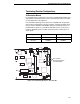
Removal And Installation
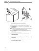
The procedure for removing and installing terminating resistors is provided in
your Maintenance Manual.
CAUTION
This is an involved maintenance procedure. To avoid damage to the
equipment, only a trained technician should perform this procedure.
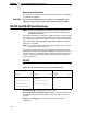
RS-232 And RS-422 Serial Interfaces
NOTE: The RS-232 and RS-422 serial interface circuit characteristics are
compatible with the Electronic Industry Association Specifications
EIA-232-E and EIA-422-B.
The RS-232 and RS-422 serial interfaces enable the printer to operate with bit
serial devices that are compatible with an RS-232 controller. The input serial
data transfer rate (in baud) is selectable from the printer's control panel. Baud
rates of 600, 1200, 2400, 4800, 9600, 19200, 38400, 57600, and 115200
baud rates are available.
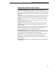
NOTE: If you select a baud rate that is greater than 19200, you may need to
use RS-422 to prevent data loss.
The length of the data cable from the host computer to the printer must not
exceed 50 feet (15 meters) for RS-232 or 4000 feet (1220 meters) for RS-422.
(A copper conductor, twisted-pair telephone cable with a shunt capacitance of
16 pF/foot [52.5 pF/meter] terminated in a 100 ohm resistive load must be
used for the RS-422.)
RS-232
Receive Data (RD). Serial data stream to the printer.
Transmit Status & Control Data (TD). Serial data stream from the printer for
transmitting status and control information to the host. Subject to protocol
selection.
Request To Send (RTS). Control signal from the printer. Subject to
configuration.
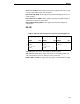
Table 7. RS-232 Serial Interface Connector Pin Assignments
Input Signals Output Signals Miscellaneous
Signal Pin Signal Pin Signal Pin
Receive Data (RD) 2 Transmit Status & Control
Data (TD)
3 Chassis/Signal Ground 5
Clear To Send (CTS) 8 Request To Send (RTS) 7
Data Set Ready (DSR) 6 Data Terminal Ready (DTR) 4
Data Carrier Detect (DCD) 1